Surface grinding machines
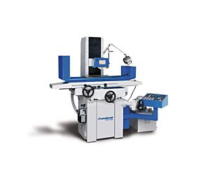
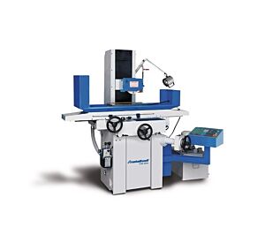
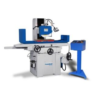
METALLKRAFT precision surface grinding machines are designed to produce flat, parallel, square or inclined surfaces with controlled geometry and a finish superior to that normally obtained by milling. The category includes machines of the same general construction but with different working capacities, axis travels, table configurations, feed systems and equipment. METALLKRAFT grinders with controlled vertical infeed allow precise management of wheel approach, stock-removal passes and final finishing stages, making them suitable for new component manufacture as well as the restoration of worn mechanical parts.
Surface grinding uses the wheel periphery to remove controlled amounts of material while the table moves the component longitudinally beneath the abrasive. Cross-feed distributes the operation across the full width, while the vertical axis determines depth of cut. These coordinated movements allow the machining of plates, blocks, guides, slides, tapered gibs, punches, dies, tools, hardened parts and precision components. Unlike ordinary surface sanding, grinding controls the geometric relationship between surfaces and can correct errors of flatness, parallelism, squareness, inclination and profile.
Before grinding, the reference surface and machining sequence must be established so that setup errors or workpiece distortion are not transferred to the finished component. The part must be clean and free from burrs, residue and particles that could lift it from the support. Even a small contaminant between the workpiece and holding system can alter the resulting parallelism. The first surface is generally ground to create a stable datum; the component is then turned or repositioned using this face as the reference for subsequent operations. The part, magnetic chuck, vice and fixtures must be cleaned before every new setup.
A magnetic chuck is the most common holding system for flat ferromagnetic workpieces. The component must have adequate supporting area, bridge the magnetic poles correctly and remain stable relative to the table movement. Long or thin workpieces require special attention because magnetic force and grinding heat can accentuate existing deformation. Rear or lateral stops can help resist tangential grinding forces, but they must not lift the component or interfere with the wheel. After machining, demagnetisation may be required to prevent the part from retaining abrasive particles or metallic debris.
Small, non-magnetic, cylindrical or irregularly supported parts can be held in precision grinding vices, V-blocks, angle plates, support blocks and dedicated fixtures. A vice must be clean, verified and seated correctly on the magnetic chuck. Clamping force must not distort the component. Thin sections may bend between the jaws and return to their original shape when released, leaving a geometrically incorrect ground surface. For small parts, a purpose-built fixture that distributes clamping force and provides a repeatable datum is preferable.
Inclined parts can be ground with an adjustable magnetic chuck, sine vice or sine bar positioned on the magnetic table. A sine bar uses precision gauge blocks to establish a controlled angle. Before grinding begins, the operator must check fixture stability, total setup height, wheel path and possible interference. Alignment should be verified with a dial indicator along the reference surface because a small angular setup error can create a significant variation over the full component length.
Dovetail slides require a carefully planned sequence. The main flat surface should be restored before the inclined faces so that a coherent datum structure is established. Sine vices, sine bars, adjustable tables or shaped fixtures can hold the slide at the required angle while its dovetail faces are ground. Straightness, parallelism between the sides and the relationship between the inclined surfaces and slideway must be controlled together. A visually polished surface is not sufficient: an attractive finish can still contain geometric errors that impair movement, adjustment and load distribution.
When rebuilding machine-tool slides, the complete kinematic system must be considered rather than only the visibly worn surface. Grinding a guideway changes the relative heights of axes, feed screws, nuts, racks, supports and mating faces. Wear, twist and geometric variation should therefore be measured along the full travel before stock is removed. Grinding may need to be followed by scraping, restoration of bearing areas, gib adjustment and a complete alignment inspection. Correcting one isolated surface without a geometric plan can transfer the error elsewhere in the machine.
Tapered gibs must retain the correct taper, straightness and relationship between their functional faces. Adjustment occurs through longitudinal displacement, so an uncontrolled change in angle or thickness alters the adjustment range and bearing contact. The gib may be held on a sine bar, in a sine vice or on a dedicated fixture, with the angle checked by indicator. Allowance may need to remain for subsequent scraping and fitting. Contact should be verified using marking blue, and slide movement should be checked over its entire travel.
Grinding-wheel selection depends on material, hardness, stock allowance, contact area, required finish and workpiece rigidity. Aluminium-oxide wheels are commonly used for unhardened and hardened steels and many tool steels, with the appropriate grade and structure selected for the application. Silicon carbide may be suitable for cast iron, brittle materials and selected non-ferrous metals. Diamond wheels are generally preferred for tungsten carbide, while CBN wheels may be suitable for high-speed steels and hardened ferrous materials. Diamond use on ferrous materials must be evaluated carefully because of the interaction between abrasive and workpiece at grinding temperatures.
Coarse grit supports stock removal and provides more space for grinding debris, while fine grit improves finish but can load and generate excessive heat if used with unsuitable infeed or contact pressure. Wheel grade indicates how firmly the bond retains the abrasive grains and does not describe the hardness of the abrasive itself. Hard workpiece materials often require a relatively softer wheel so that worn grains are released and fresh cutting edges are exposed. A wheel that is too hard may glaze, stop cutting and overheat the component; a wheel that is too soft may wear rapidly, lose its profile and require frequent dressing.
Dressing restores wheel sharpness, flatness and open structure, while truing or profiling corrects concentricity and working geometry. A freshly dressed wheel cuts freely and is suitable for stock removal. A finer dressing condition can improve finish, provided it does not close the wheel surface excessively. The dresser must be stable and positioned correctly relative to the direction of rotation. After substantial dressing, the dimensional change must be compensated before the grinding cycle resumes.
A controlled cycle normally progresses through roughing, semi-finishing, finishing and spark-out. Roughing removes most of the allowance using a freely cutting wheel and passes compatible with machine and workpiece rigidity. Finishing passes progressively reduce infeed. During spark-out, table movement continues without additional downfeed, allowing elastic deflection and residual irregularities within the system to diminish. Excessive spark-out does not necessarily improve the surface and may polish the wheel or generate unnecessary heat.
Coolant control is essential for limiting thermal expansion, grinding burn, microcracking and metallurgical change. Fluid should reach the contact zone directly with a continuous and coherent flow that is not deflected by wheel rotation. Intermittent coolant can create damaging thermal cycles, especially on hardened materials and carbide. Filtration prevents abrasive grains and metallic residue from returning to the contact area and scratching the finished surface. A magnetic separator can assist with ferrous contamination, while the selected coolant must remain compatible with the wheel, workpiece and machine.
Sharpening profiled tungsten-carbide tools used on single-spindle and multi-spindle automatic lathes requires diamond wheels, rigid fixtures and references capable of reproducing profile, clearance angle and cutting-edge position. Tool blanks should be supported close to the grinding area to minimise vibration. Precision vices, angle plates and adjustable devices can be used for simple profiles; complex geometries may require profiled wheels, templates, profile projectors or dedicated tool-grinding fixtures. A surface grinder can produce compatible flat surfaces and profiles, but tools with multiple relief angles or complex cutting edges require an appropriate sharpening system.
Regrinding must reproduce more than the tool’s visible outline. Functional angles, clearance behind the cutting edge, profile position relative to the holder and strength of the remaining section must be preserved. A profiled tool used for small-component production on automatic lathes must generate the specified geometry without rubbing, vibrating or applying excessive force to the workpiece. After sharpening, the profile should be inspected, microscopic burrs removed without rounding the edge and the cutting zone checked for burn or chipping.
Manufacturing or restoring pins with different diameters, flats, chamfers or profiles requires fixtures that hold the cylindrical component and index its position. V-blocks, round-work vices, rotary fixtures, collets and indexing devices make it possible to grind opposed flats, ends and localised profiles. Where a continuous cylindrical diameter with close tolerance around the complete circumference is required, cylindrical grinding remains the correct process. A surface grinder is more suitable for flats, slots, profiles and diameter-related operations carried out through specialised fixtures and controlled rotation.
Inspection should be performed with the workpiece thermally stable and all surfaces clean. Flatness and straightness may be checked using a surface plate, precision straightedge, indicator and marking blue. Parallelism and thickness variation require suitable indicators or measuring instruments, while squareness is checked with precision squares. Angles and profiles may be verified using sine bars, gauge blocks, optical instruments or geometric measuring systems. Surface roughness must be evaluated separately from geometry because a very fine finish does not automatically guarantee flatness, parallelism or an accurate profile.
METALLKRAFT surface grinding machines are used in toolrooms, precision engineering workshops, mould and die production, machine-tool manufacture and rebuilding, industrial maintenance and the automotive, aerospace, railway, energy and general engineering sectors. Typical components include dies, punches, plates, guides, slides, tapered gibs, profiled tools, carbide blanks, hardened parts, small metal components, pump and valve parts, workholding equipment and components used in cookware and household-accessory production. In foundries they are employed to restore functional surfaces, mould components and parts intended for precision assembly.
Purchasing decisions should consider magnetic-chuck capacity, usable travels, clearance under the wheel, column rigidity, base stability, feed accuracy, vertical-axis control, spindle quality and table-motion system. Magnetic workholding, coolant and filtration equipment, wheel dresser, guards, lighting, dimensional display, maintenance access and the availability of wheels and spare parts should also be assessed. Selection must reflect not only the largest components but also the smallest and most delicate parts that need to be held and inspected reliably.
Tadaah supports the selection of METALLKRAFT surface grinding machines by evaluating workpiece materials, geometries and dimensions, required tolerances, finish level, holding equipment and operating frequency. The correct solution results from integrating the grinder with the magnetic chuck, precision vices, sine bar, round-work fixtures, grinding wheel, dresser and coolant system. This approach identifies equipment suited to professional production, maintenance, machine rebuilding and tool-sharpening requirements.
URL: surface-grinding-machines
Meta title: Professional Precision Surface Grinding Machines
Meta description: Precision surface grinders for flat surfaces, dovetail slides, tapered gibs, profiled tools and accurately finished mechanical components.
Keywords: surface grinding machines, surface grinder, precision surface grinders, flat surface grinding machine, tangential grinding machine, magnetic chuck surface grinder, NC vertical infeed grinder, machine slideway grinding, dovetail slide grinding, tapered gib grinding, profiled tool grinding, tungsten carbide tool sharpening, carbide form tool grinding, punch and die grinding, precision grinding, small metal component grinding, diamond grinding wheel for carbide, CBN grinding wheel, sine bar grinding setup, precision grinding vice, adjustable magnetic chuck, pin grinding fixtures, METALLKRAFT surface grinders, PRORA BETA grinder, PRORA BETA grinding machine, PRORA BETA surface grinder alternative