DRILLING
TWIST DRILLS
Twist drills are cutting tools designed to create holes using machine tools such as lathes, machining centers, milling machines, drills, and drill presses. They are used to manufacture products in the mechanical, dental, automotive, plumbing, hydraulic, valve, appliance, and power tool industries. These drills are also employed by freelancers for assembly, repairs, prototyping, and hobbyist projects. Being highly versatile and widely used, twist drills have undergone significant evolution over time, allowing users to choose from a broad range of options.
The selection of a twist drill is based on several criteria, which we list below:
- Material of the workpiece to be drilled
- Drill diameter
- Drilling depth
- Type of drill cooling
- Coolant pressure
- Production quantity
- Type of machine use
Frequency of use
Once the exact application is determined, we can select the drill that best fits our needs. During this selection, it’s important to consider that drills come with different features and quality levels, resulting in a wide price range.
To provide a general idea of the extensive variety of drills, we can mention some key technical specifications that distinguish them:
- Drill material
- Drill coating
- Helix angle
- Flute geometry
- Sharpening type
- Point angle
- Flute surface roughness
HSS TWIST DRILLS
HSS (High-Speed Steel) and HSCO (Sintered High-Speed Steel) twist drills are commonly used today for maintenance operations, tooling applications involving single-piece production on easily machinable steels, and by automotive mechanics for minor car or bodywork repairs. Their advantages include being extremely cost-effective and durable. They are often sold in sets with various diameters.
These drills can also be used on non-precision automatic machines. In cases where there is misalignment between spindles, the drills often wobble off-center without breaking.
They can also be used with a high helix angle for drilling lightweight alloys.
CARBIDE TWIST DRILLS
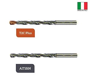
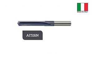
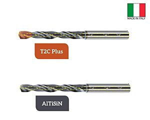
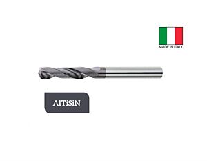
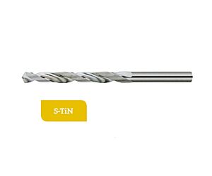
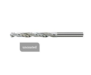
Carbide twist drills are currently the most widely used type for all machine tool applications. They offer a broad range of uses, delivering high performance and cost-effectiveness for large production batches, as well as frequent use in small to medium production runs. These drills are suitable for machining all types of materials and alloys, including hardened workpieces and high-hardness materials. They come in a wide variety of point geometries.
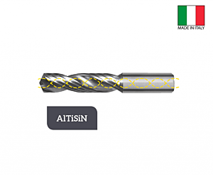
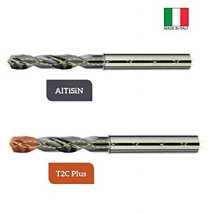
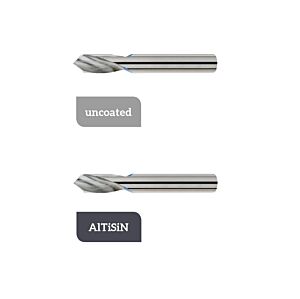
Many carbide drills feature internal coolant channels for high-pressure coolant delivery. Additionally, they are available in different carbide grades and coatings to enhance performance and extend tool life between sharpenings.
In some cases, they are used to modify heat-treated parts. However, for such applications—particularly when drilling into case-hardened and tempered workpieces—they should primarily be used on CNC machines. This is because the consistent feed rate provided by CNC controls prevents drill breakage during the critical transition from drilling the hardened surface to the softer core material.
HOW A TWIST DRILL IS MANUFACTURED
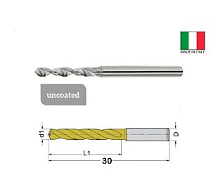
A twist drill is produced from a solid carbide cylinder, typically made of tungsten carbide with varying grain sizes and bonded with the same matrix materials used for cutting tools, milling inserts, and turning tools.
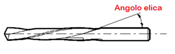
The carbide blank is precision-ground with a two-flute helix, while maintaining a perfectly cylindrical h6-tolerance shank for secure clamping in the tool holder. The helix is machined with a pitch determined by a specific inclination angle known as the helix angle.
The helix angle, flute length, and flute profile are all customized based on the workpiece material being machined.
CARBIDE TWIST DRILLS
Carbide twist drills have become the industry standard for machine tool applications due to their versatility, high performance, and cost-efficiency—whether for large production batches or smaller recurring orders. These drills handle all material types, including hardened workpieces and high-hardness alloys, and are available with diverse point geometries. Many feature internal high-pressure coolant channels and specialized carbide grades with performance-enhancing coatings to maximize tool life between regrinds.
They’re particularly valuable for modifying heat-treated components, though such operations should strictly use CNC machines—especially when drilling case-hardened parts. The CNC’s controlled feed rate prevents tool breakage during the critical transition from hardened surfaces to softer core material.
TWIST DRILL MANUFACTURING PROCESS
The production begins with a tungsten carbide cylinder, mirroring the composite structure of cutting inserts. Precision grinding forms a two-flute helix while maintaining an h6-tolerance shank for vibration-free clamping. The helix geometry—its angle, length, and flute profile—is tailored to the workpiece material.
Helix Design Considerations
The helix configuration dictates chip evacuation efficiency and directly impacts cutting performance. Flutes are machined to an ultra-smooth finish (typically under Ra 0.4) to minimize chip friction. Improper helix angles, rough surfaces, or excessive feed rates will impede chip flow and cause catastrophic tool failure. While wider flutes improve chip clearance, they reduce structural rigidity; insufficient feed rates then risk thermal degradation of the carbide binder.
Precision Engineering Features
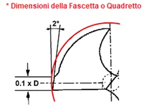
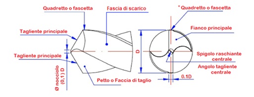
A subtle back taper prevents margin drag against hole walls during operation. More critically, each flute incorporates a precision-ground margin (0.1–0.2x drill diameter) offset 50% above the centerline with 2° clearance. This design achieves three vital functions: stabilizing the drill against rotational forces, maintaining hole dimensional accuracy, and neutralizing torsional stresses that could fracture the tool. The margin’s engineered position is what allows consistent performance when drilling hardened materials or deep cavities where torque fluctuations would otherwise cause premature failure.
Drill Point Geometry and Sharpening Techniques
The creation of the margin along the flute, being machined above the centerline, automatically forms a solid central core known as the "web thickness." This web area represents the least efficient cutting portion of the drill due to its near-zero cutting velocity - essentially, this central zone doesn't cut but rather pushes through the material. During primary cutting edge sharpening, this web naturally creates what's known as the "chisel edge angle."
To ensure proper material penetration and efficient drilling, precise point sharpening is critical. The process begins with establishing the primary cutting edge angle (∂), which simultaneously forms the leading edge. This sharpening operation demands extreme precision, requiring both cutting edges to be perfectly identical and symmetrical.
A fundamental rule must always be observed regarding the relationship between cutting edges: the distance from edge point 1 to the drill axis (S1) must always be shorter than the corresponding distance from edge point 2 (S2). This S1 < S2 condition is essential for maintaining proper cutting geometry and drill performance.
The web thickness, while necessary for structural integrity, presents particular challenges during the cutting process. As material is compressed rather than sheared in this central zone, proper point geometry becomes crucial to minimize thrust force requirements and prevent work hardening of the material being drilled.
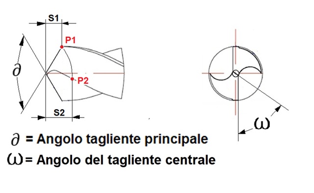
The optimal angle of the primary cutting edge varies according to specific drilling requirements. This critical angle is typically adjusted based on the drill diameter to achieve optimal performance. For smaller diameter drills ranging from 1mm to 3mm, a 120° point angle is standard, as this configuration helps maintain proper alignment during operation.
As drill diameters increase to between 3mm and 4.5mm, the recommended point angle expands to 130°. For larger drills exceeding 4.5mm diameter, a 140° angle becomes preferable. This progression reflects the changing mechanical requirements - smaller drills benefit from more acute angles to prevent wandering, while larger diameter tools can utilize more obtuse angles since their inherent rigidity minimizes deflection concerns.
The wider 140° angle on larger drills offers the additional advantage of reducing the axial force required for penetration into the workpiece material. This graduated approach to point geometry ensures each drill size operates with maximum efficiency while minimizing potential operational challenges.
The accompanying illustration provides a comprehensive visual representation of all key characteristics that define twist drill geometry, including these critical angular relationships and their impact on drilling performance. This systematic approach to point angle selection helps optimize drilling operations across the full range of tool sizes and applications.
Types of Primary and Chisel Edge Sharpening Geometries
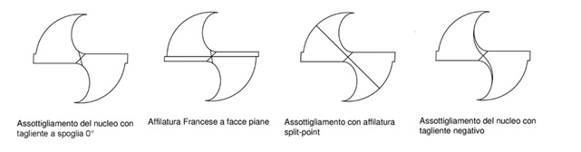
Various sharpening configurations exist for twist drills, each specifically designed to match different workpiece material characteristics. These specialized point geometries serve multiple critical functions - they create ample space for efficient chip evacuation while simultaneously enhancing the structural integrity of the primary cutting edges. The designs particularly focus on optimizing the chisel edge geometry by thinning the web thickness as much as possible, creating a sharper central cutting point that significantly reduces the thrust force required when drilling into solid material.
The different sharpening profiles illustrated each represent solutions to specific machining challenges. Some geometries prioritize maximum strength for hard materials, while others emphasize chip clearance for gummy alloys. What unites them all is the careful balance between maintaining tool rigidity and minimizing cutting resistance at the critical center point where conventional drills typically encounter their greatest penetration challenges. These advanced point designs effectively transform what is normally a crushing action into a more efficient cutting motion at the drill's center.
FORCES APPLIED DURING DRILLING
There are mainly two forces at work during drilling:
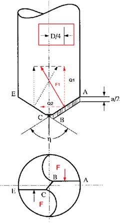 The force F1 develops along the cutting face (within the helix plane), originating at a point located at one-quarter of the drill diameter (Ø/4) and aligned perpendicular to the bisector of the primary cutting edge angle. This force system generates a resultant vector directed toward the drill axis, preventing tool oscillation and ensuring precise hole formation in the workpiece.
The relationship between point geometry and drilling stability becomes evident—an excessively wide point angle induces drill wandering as the tool tends to deviate from center, while an overly acute angle increases thrust pressure on the web area, potentially leading to fracture. The direction of F1 varies significantly with changes to the primary cutting edge's sharpening angle.
Simultaneously, the resultant force F creates a downward deflection from the ideal frontal axis. To counteract this effect—along with compensating for centrifugal forces during rotation (particularly critical in lathe operations)—the margin (land) feature was engineered. The magnitude of these forces depends fundamentally on the material's specific cutting resistance (Ks factor) and can be resolved into two distinct components: radial force Q1 and stabilizing force Q2.
A critical mechanical interaction emerges as the primary cutting angle increases—Q1 diminishes while Q2 rises proportionally. This force redistribution affects central stability during drilling, suggesting that under certain conditions with sufficiently acute angles, the drill could theoretically provide supplemental support during light external turning operations performed concurrently with drilling. Specialized point geometries may be employed to optimize this effect when using profiled drills.
Ultimately, force F represents the essential cutting force used to calculate both drilling torque requirements and power consumption, forming the foundation for process optimization and tool performance analysis. The careful balancing of these forces through precise point geometry selection ensures efficient material removal while maintaining dimensional accuracy and tool integrity.
Complete Drilling Calculation Formulas
This section presents the essential formulas for calculating drilling parameters across various materials, including cycle time estimation based on previously referenced tables. We will examine detailed calculations for power requirements, torque, and feed force—critical data for determining whether the drill can withstand radial machining loads and whether the collet provides sufficient clamping force to prevent tool slippage. These calculations must also account for any additional radial loads from secondary tools and verify adequate motor power for the drilling operation.
Key Parameters:
- Rotational speed (n)
- Drill diameter (Øp)
- Cutting speed (Vt)
- Mean cutting speed (Vm = Vt/2)
- Feed per revolution (a)
- Chip cross-section (A, in mm²)
- Material removal rate (Q, in cm³/min)
- Motor power (Pmot)
- Torque/clamping moment (Mc, in Nm)
- Feed force (Ff, in N)
- Chip thickness (h, in mm)
- Specific cutting force (F, in N/mm²)
- Feed rate (Vs, in mm/min)
- Motor efficiency (η)
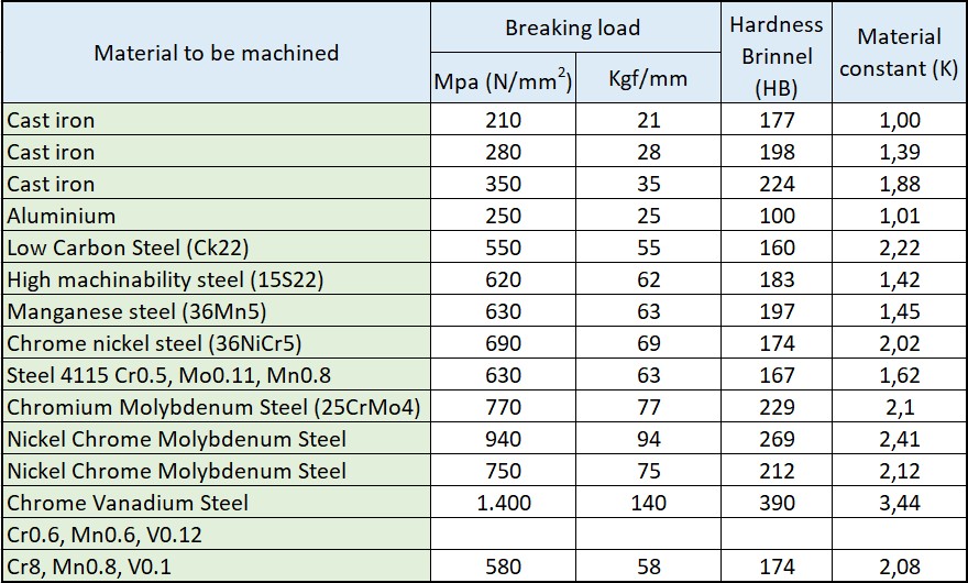
- Material compensation constant (K)
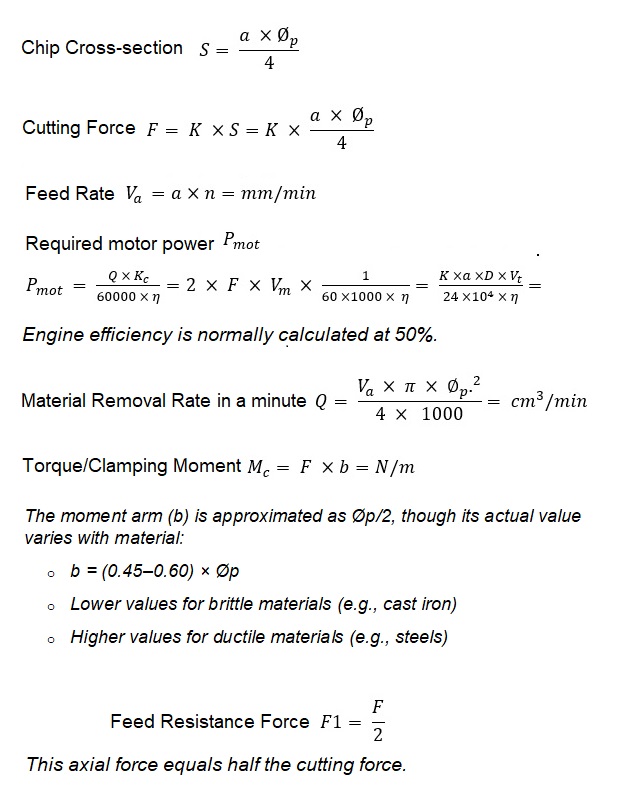
These formulas provide a systematic approach to optimizing drilling operations while ensuring tool integrity and process stability. The variable moment arm (b) and material-specific constants (K) enable tailored calculations for diverse machining conditions.
Chip Formation in Drilling Operations
The relationship between chip morphology and cutting parameters plays a crucial role in drilling performance. The accompanying illustrations demonstrate how chip shape transforms with variations in feed rate and cutting speed. Proper parameter selection enables controlled chip formation—at low speeds and feeds, chips appear whitish with gradually elongated tails, while increased parameters produce compact, glossy chips. These morphological changes stem from cutting temperature variations, where elevated temperatures promote chip fracturing. Certain steel and aluminum alloys, however, consistently generate long chips regardless of machining parameters.
Conventional Regrinding of Carbide Drills
While carbide drills can be reground and refurbished, they typically experience a 30% reduction in efficiency post-sharpening. This performance degradation presents significant challenges for high-volume manufacturers, who often opt for tool replacement rather than regrinding to maintain production quality. Three primary factors contribute to this efficiency loss:
Excessive cutting edge wear beyond 0.15mm compromises tool integrity by oxidizing and softening the binder phase (typically cobalt), which can dislodge tungsten carbide particles. The grinding process itself generates temperatures reaching 500-600°C, potentially re-oxidizing the binder and damaging coatings—particularly problematic when removing thin coatings (≈0.003mm) that approach the binder's oxidation threshold.
Coating reapplication may create excessive thickness, dulling the cutting edge and generating operational heat that further reduces tool life. Additionally, grinding-induced micro-burrs on primary edges can initiate carbide particle detachment, leading to premature tool failure.
Advanced Regrinding and Cutting Edge Restoration
Achieving new-tool performance through regrinding requires specialized procedures to restore binder stability and recoating integrity. This precision work demands expert handling, and while the process is complex, Tadaah provides technical criteria for optimal results along with post-sales support.
Critical success factors include maintaining pre-grinding wear below 0.15mm and employing fine-grit diamond wheels with controlled temperature management. For coatings exceeding 5μm thickness, chemical or EDM removal proves necessary. Post-grinding inspection under 20-50X magnification ensures complete coating removal, followed by ultrasonic acetone cleaning. Thermal reconditioning becomes mandatory if temperatures exceed 500°C during grinding.
The process concludes with honing to eliminate micro-burrs and precision recoating. While this comprehensive approach exceeds standard regrinding costs, it delivers performance approaching new tools—an investment justified for premium carbide drills in critical applications.
Technical Note: The described methodology requires specialized equipment and expertise, making it most suitable for high-value tools where performance justifies the additional processing costs.