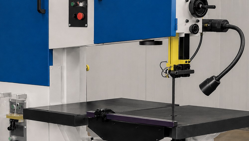
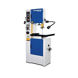
METALLKRAFT, NEBES Elettromeccanica and OPTIMUM vertical metal-cutting band saws are designed to produce straight, curved, contoured and, with appropriate equipment, internal cuts in plates, blocks, profiles and metal components. Unlike horizontal saws, where the saw frame descends onto material held in a vice, a vertical saw keeps the blade in a fixed cutting position while the workpiece is guided across the table. This configuration provides considerable operating freedom and allows the user to follow outlines, contours and profiles that cannot be produced through a simple cut-off operation.
Machines within the category share the same general operating principle but differ in table size, working height, cutting capacity, structural rigidity, speed regulation, workpiece-feed system and equipment. Compact models are suitable for maintenance, small-component work and occasional profile preparation. More substantial vertical saws meet the requirements of toolrooms, mould-making departments, fabrication shops and workshops that process plates, patterns and components continuously. Depending on the model, equipment may include manual or controlled table feed, a tilting table, work lighting, cooling, chip blowing and integrated blade cutting, welding and finishing units.
Before cutting begins, the machine must be installed on a stable and level surface. The table should be free from chips and residue that could tilt the component or scratch its surface. The cutting line must remain clearly visible and, where accuracy is important, should include the stock allowance required for subsequent milling, grinding or finishing. The blade should not be forced directly onto a finished dimension when the specified geometry or tolerance can only be achieved by a later machining process.
During manual cutting, the component should rest fully on the table and be guided with both hands positioned to either side of the blade path. Pressure must be even and directed along the feed direction without side-loading the band. Large or heavy workpieces need external supports at the same height as the table so that their weight does not cause inclination. Small, thin or difficult-to-hold parts require push devices, clamps, templates or dedicated fixtures that keep the operator’s fingers away from the blade.
A straight cut can be supported by a rip fence or rigid guide where provided. The workpiece should advance without abrupt corrections because a cut that has already deviated cannot be recovered by forcing the blade sideways. For repeated components, a stop or template improves positional and angular consistency. Where the machine has controlled table feed, the workpiece must be secured with suitable clamping and the feed adjusted to the material, thickness and tooth pitch.
Curved cutting requires a blade narrow and flexible enough for the specified radius. A wide blade provides better stability in straight cuts but cannot follow a curve below its permissible radius without twisting and overloading. Relief cuts in the waste area can divide a complex contour into manageable sections and prevent scrap from trapping the blade as the component is turned. The workpiece should rotate progressively around the cutting area without using the back of the blade as a lever or forcing a curve tighter than the blade width allows.
Vertical saws can also produce closed internal cuts when equipped for blade cutting and welding. A starting hole is drilled inside the area to be removed, the blade is opened, passed through the hole and rejoined to form a continuous loop. The weld must be aligned, annealed and finished correctly, without steps, offset or excess thickness that could strike the guides. Once the internal profile has been completed, the blade is opened again so that the component can be removed.
Blade welding requires clean, square ends positioned in accurate alignment. An offset joint produces vibration, noise and periodic load on the guides. A brittle weld may fail during operation, while a joint that is not properly annealed can retain excessive stress. The weld bead must be dressed without reducing the load-bearing section of the blade. Before installation, the joint should be checked for cracks, distortion and free passage through the guides.
Blade selection must consider workpiece material, thickness, profile shape, minimum radius and required finish. Wider blades are appropriate for straight cuts and substantial sections, while narrower bands facilitate curves and contours. Tooth pitch that is too coarse for thin sheet leaves too few teeth engaged and can cause snagging, vibration or tearing. Pitch that is too fine for thick solid material provides insufficient gullet capacity, leading to packed chips, heat and cutting deviation.
Bimetal blades provide a versatile solution for carbon steels, alloy steels, stainless steels and many non-ferrous materials. Variable-pitch teeth help reduce vibration and noise where the engaged section changes. Particularly hard, abrasive or difficult-to-cut materials may require specialised or carbide-tipped blades, provided the machine has suitable speed, rigidity and blade guides. Blade length, width, thickness, tooth direction and weld characteristics must comply with the METALLKRAFT, NEBES Elettromeccanica or OPTIMUM machine specification.
Blade speed must suit the material. Hardened steels, stainless steels and tough alloys generally require lower speeds, whereas aluminium, brass and more readily machinable materials may permit higher speeds. Continuous or multi-range regulation improves adaptability to different processes. Speed should not be selected only to shorten cutting time: an unsuitable setting can overheat the teeth, accelerate wear, impair the finish and make workpiece guidance more difficult.
Operator pressure or powered feed should produce a regular, formed chip. Insufficient feed causes rubbing rather than effective cutting, promoting blade wear and work hardening. Excessive pressure can bend the blade, divert the cut, strip teeth or overload the guides. Fine dust may indicate a worn blade or insufficient feed, while heavily coloured, distorted or welded chips can indicate excessive temperature, unsuitable speed or inadequate cooling.
Cooling may be provided through coolant, mist or an air jet, depending on machine configuration. Coolant reduces friction and temperature and assists chip removal. A chip blower keeps the marked line visible and prevents residue from building up in front of the teeth. The jet should be directed without obscuring the work or throwing chips toward the operator. Liquids must not be added to machines designed for dry cutting unless their use is specifically approved by the manufacturer.
A new blade requires break-in under reduced feed and load. During the initial cuts, the tooth edges stabilise and become less vulnerable to microscopic chipping. Feed can be increased progressively after this period. Starting immediately on material with a hard skin, irregular surface or heavy oxidation can damage the blade prematurely. Correct break-in improves working life and helps maintain stable cut quality.
The upper blade guide should be lowered close to the workpiece, leaving only the clearance required for the component. Excessive distance increases the unsupported blade length and encourages deflection and vibration. Side and rear guides must support the band without preventing its movement or altering the blade path. Tension must correspond to the machine requirements: insufficient tension encourages wandering, while excessive tension overloads the weld, wheels and bearings. Adjustments must be performed with the machine stopped and isolated from its power supply.
Depending on the model, the worktable may be fixed or tilting. Tilting makes it possible to produce bevelled edges and angular cuts while the blade remains vertical. Before adjustment, the table must be supported, references cleaned, the angle set and all locks secured. An inclined table changes the way the workpiece rests and may encourage it to slide, requiring guides, fixtures or other holding methods. The first component should be inspected with a suitable measuring tool before a production batch is started.
Controlled table feed can maintain a consistent rate at which material enters the blade. This is useful for heavy plates, long straight cuts and repetitive work. The component must be secured to the table and the entire travel path kept free of interference. Powered feed cannot compensate for an unsuitable, worn or incorrectly adjusted blade; tooth pitch, tension, guide position and speed must still be correctly selected.
Routine maintenance includes cleaning the table, blade guides, wheels and lower cabinet, where chips and residue can accumulate. Blade tension, teeth, weld, alignment, wheel surfaces, bearings, guards and controls require regular inspection. Blade-cleaning brushes should clear the gullets without excessive pressure. Coolant must remain at the specified level and concentration, while hoses, nozzles and pump must be kept clean. A blade with missing teeth, cracks, a defective joint or permanent distortion must be replaced.
Purchasing decisions should consider component size and weight, common material thicknesses, requirements for curved or internal cuts, minimum radii, table tilt and expected productivity. Structural rigidity, base stability, table dimensions and load capacity, clearance beneath the upper guide, speed regulation, cooling, lighting, table feed and the availability of an integrated blade welder are also important. Blade availability, maintenance access and the space required for handling components should be included in the evaluation.
METALLKRAFT, NEBES Elettromeccanica and OPTIMUM vertical metal-cutting band saws are used in toolrooms, machine shops, mould-making departments, industrial maintenance and machine-tool rebuilding. Applications include metal fabrication, structural-steel work and the production of templates, patterns, plates, flanges, supports, curved elements and components intended for milling, welding or assembly. They are also used in automotive, railway, aerospace, energy, plant engineering and prototype production.
Vertical band-saw flexibility results from the ability to machine external and internal profiles, follow straight or curved paths, tilt the table and select different blades for geometry and material. Final quality depends on the balance between blade width, tooth pitch, speed, tension, guides, cooling and feed technique. A correctly configured machine reduces waste and secondary operations, improves contour control and prepares complex components efficiently.
Tadaah supports the selection of METALLKRAFT, NEBES Elettromeccanica and OPTIMUM vertical metal-cutting band saws by evaluating material, thickness, dimensions, profile geometry, internal-cut requirements, minimum radius and operating frequency. The correct solution integrates machine structure, table, feed, blade, tooth pitch, speed, guides, blade welder and cooling system to provide a configuration genuinely suited to professional requirements.