Accessories and spare parts for bench grinders
Accessories and spare parts for bench grinders include components used to install the machine correctly, control its starting and stopping, protect the operator, support the workpiece and manage dust, sparks and grinding residue. Pedestals, control units, braking devices, wheel guards, work rests and extraction-ready guards perform different functions and are not automatically interchangeable. Every component must be selected according to the grinder model, spindle arrangement, installed wheels, electrical system and intended operation.
A compatible accessory does more than complete the machine; it directly contributes to stability, precision and safety. A correctly matched pedestal keeps the grinder at a suitable working height and limits vibration and movement. A wheel guard encloses the non-working portion of the abrasive and helps deflect fragments. A control unit organises machine commands and may integrate starting, stopping, isolation and, where provided, braking functions. A guard with an extraction connection helps capture dust and particles near their point of generation.
Spare-part selection should begin with precise machine identification. Manufacturer, series, configuration, mounting position, machine side, fixing pattern and original component reference should be checked. Guards that appear similar can have different mounting holes, thicknesses, connections or internal profiles. A pedestal described as broadly compatible must still be checked against the grinder base, machine weight, load distribution and anchoring method.
Compatibility must include mechanical fit, structural strength, wheel clearance, guard position, freedom of rotation, control accessibility and maintainability. Electrical replacement parts also require verification of the circuit, power supply, connections, protective functions and control logic. Components affecting starting, emergency stopping or braking should be installed by qualified personnel and followed by functional testing.
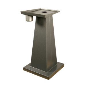
Grinder pedestals convert a bench-mounted machine into an independent workstation. The structure must be rigid and placed on a strong, level surface. Its base should be anchored according to the manufacturer’s instructions so the machine cannot move, rock or rotate during use. The grinder must also be fixed securely to the upper mounting plate using every intended fixing point.
Working height should allow the operator to maintain a natural posture through the back, shoulders and wrists. A position that is too high forces the arms upward and reduces control, while a low position encourages bending and can produce an incorrect workpiece angle. There must be enough space around the pedestal to manoeuvre long or bulky components without striking walls, equipment, cables or other operators.
A pedestal intended for fixed machinery should not be treated as a mobile stand. Grinding forces can cause an unanchored structure to walk across the floor. Abnormal vibration can impair the finish, wear the wheel unevenly and loosen fixings, guards and rests. Machine mounting, pedestal stability and anchors should therefore be inspected before operation.
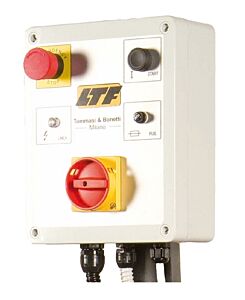
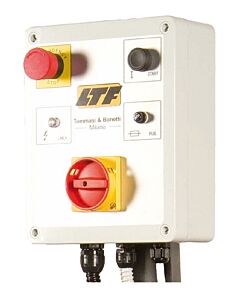
Control units bring the functions required to operate the grinder into an accessible location. Depending on the configuration, they may include start and stop controls, emergency stopping, isolation, protection against unexpected restart and management of auxiliary functions. Some versions incorporate braking intended to reduce the rundown time of rotating parts after stopping.
A brake does not make it safe to touch the wheel immediately after pressing stop. Before adjustment, cleaning, accessory replacement or maintenance, the operator must wait for complete standstill, isolate the power supply and prevent unintended restart. The brake must be compatible with the motor and inertia of the fitted accessories. An unsuitable or incorrectly configured braking system can impose abnormal loads on the spindle, flanges, wheel and connections.
Controls must be clearly identifiable, accessible from the normal working position and protected against accidental activation. The emergency stop must remain unobstructed by workpieces, tools or materials. A control unit with damaged controls, a cracked enclosure, loose cable entries or exposed connections must be removed from service and inspected.
Replacing a control unit is not simply a matter of connecting a device that appears equivalent. The electrical diagram, safety functions, motor characteristics, stopping method and coordination with other machine protections must all be verified. After installation, normal start, normal stop, emergency stop, isolation and behaviour following a power interruption should be tested.
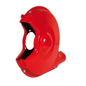
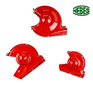
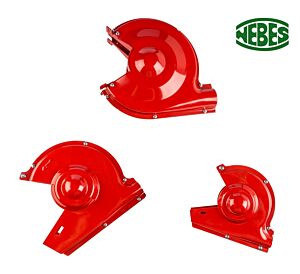
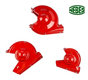
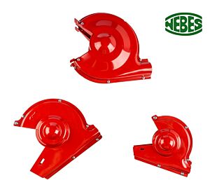
Wheel guards are fundamental grinder components. They enclose the non-working portion of the wheel, restrict access to the spindle, flanges and rotating parts, and help contain or redirect fragments if an abrasive wheel fails. Their material, shape and strength must be suitable for the machine and wheel. Guards must not be replaced with improvised covers or modified by unauthorised cutting, drilling or enlargement.
The guard must be fitted in the correct position using all intended fasteners. The wheel must rotate freely without rubbing, but the working opening must not be enlarged beyond what is required. Following guard replacement, the wheel should be turned manually with the machine isolated to confirm that no interference exists. A no-load test can then be performed with the operator outside the plane of rotation.
Extraction-ready wheel guards combine mechanical protection with dust capture. Their internal geometry guides dust and debris towards a connection for a suitable extraction system. Ducts and joints must be installed without severe restrictions, leaks or accumulations. An opening in a guard does not guarantee effective extraction if the airflow is insufficient or the collector is unsuitable for the generated dust.
Extraction compatibility depends on the material. Dust from cast iron, steel, abrasives, aluminium, light alloys, brass and bronze has different properties. Fine dust from some metals can be combustible and must not be collected indiscriminately with sparks and ferrous residue. An extraction guard is only one part of the system; extraction, separation, filtration, collection and disposal must also be suitable.
Transparent eye shields intercept some sparks and particles directed towards the operator. They should be clean, undamaged and positioned for clear visibility. A clouded, cracked or distorted screen should be replaced. These shields do not replace safety glasses or a face shield and should not be removed merely to improve visibility.
Work rests are adjustable components subject to wear. They must be rigid, free from deformation and capable of being locked without play. The supporting surface should hold the component at the point where it meets the wheel and help maintain the required angle. A bent or worn rest, or one with damaged fixings, makes workpiece control difficult and increases the risk of catching.
Clearance between the rest and wheel should be kept as small as practicable while complying with the manufacturer’s instructions and applicable safety requirements. Excessive clearance may allow the workpiece to become trapped, while insufficient clearance can cause contact between the parts. As the wheel becomes smaller through use and dressing, the rest must be inspected and readjusted with the machine stopped.
Upper adjustable guards must also follow wheel wear. Leaving an excessive opening reduces protection. After wheel replacement or dressing, the work rest, upper guard, transparent shield and side guard should all be inspected. No adjustment should be made while the abrasive wheel is moving.
Wheel selection remains important when purchasing accessories and spare parts. The guard, flanges, work rest and grinder must be compatible with wheel shape, width, bore, abrasive type and operating conditions. A wider or differently shaped wheel must not be installed merely because it fits the spindle. If installation requires removing a guard, omitting a blotter, modifying a flange or moving the guard beyond its intended range, the combination is incorrect.
Aluminium oxide wheels are commonly used for steels. Cast iron, aluminium, brass, bronze and other non-ferrous materials may require silicon carbide or another abrasive explicitly approved by its manufacturer. A coarse grit supports rapid removal, while a fine grit offers greater control. Grade, structure and bond should be selected according to material, contact area, amount of flash and cooling method.
Accessories should allow the operator to use the wheel without adopting an unsafe position. The component is supported on the adjustable rest and guided towards the front peripheral surface of the wheel. Contact should occur within the intended working area. The side face of a straight wheel must not be used unless expressly designed for side loading.
When removing a burr, the component should be oriented so the projection meets the abrasive progressively. Pointing the edge into the wheel rotation can cause catching. A constant inclination should be maintained when producing a chamfer, using the rest as a reference. Extended edges should be moved laterally across the wheel face to distribute wear.
Small, thin, hot or difficult-to-hold components require suitable pliers or fixtures. A workpiece must not be supported on a guard surface that was not designed as a rest, nor inserted into openings between the guard, flange and wheel. A correctly selected accessory should improve control without creating additional trapping points.
When fettling foundry castings, parting lines, gate remnants, feed-system residue, flash and oxides should be removed progressively. A stable pedestal and correctly adjusted rest improve control of heavy or irregular castings. The wheel guard protects the non-working area and, where prepared for extraction, helps direct dust and debris towards the capture system.
Cast-iron parts can produce graphite-rich residue. Aluminium and light alloys can load an unsuitable wheel and generate dust requiring specific controls. Brass and bronze should be ground with moderate pressure. Accessories do not make a grinder universal: wheel, guard and extraction must remain compatible with each material.
In cookware, tableware, cutlery, handle, tap and household-accessory production, stable rests and intact guards assist in removing casting or stamping burrs without damaging visible surfaces. A correctly organised workstation improves repeatability when preparing edges and gate areas for later satin finishing, brushing or polishing.
Workpiece temperature should be controlled through short contacts, moderate pressure and frequent pauses. Where material and process permit, the part may be cooled in a separate container, ensuring that water or coolant cannot reach a dry-running wheel, control unit, motor or electrical component. Cooling trays, pipework or systems not intended by the manufacturer should not be added without verifying machine compatibility.
Hardened tools and thin components may suffer thermal shock, distortion or loss of hardness. Discolouration around a cutting edge may indicate overheating. A correctly dressed wheel and stable work rest permit light, controlled passes and reduce the need for excessive pressure.
Dressers, flanges, bushings, blotters, clamping devices and mounting tools are additional parts that affect grinding quality. A dresser restores wheel concentricity and cutting ability; flanges and blotters distribute clamping pressure; bushings and adapters permit only expressly approved combinations. Deformed, corroded or worn parts must be replaced rather than compensated for with improvised shims.
Before returning the machine to service after a replacement, all fixings, wheel clearance, guard and rest positions and control functions must be checked. A no-load test should confirm vibration, noise, runout, stopping behaviour and, where fitted, extraction performance. The grinder should not be used if the replacement adversely affects a protective function.
Preventive maintenance includes checking pedestal anchors, inspecting guards and shields, cleaning ducts, examining work rests, testing controls and inspecting cables. Original or expressly compatible spare parts restore the intended configuration without improvised modifications. Retaining documentation, component references and maintenance records makes future identification more reliable.
Accessories and spare parts for bench grinders are used in engineering workshops, foundries, fabrication, toolrooms, mould making, valve and tap production, industrial and agricultural maintenance, automotive manufacturing and the production of cutlery, cookware, tableware, handles, hinges, furniture fittings and decorative articles.
Professional selection treats the grinder as a complete system formed by the structure, motor, controls, wheel, flanges, guards, rests and extraction. Installing the correct component preserves stability, protection and functionality. Choosing a part only because it appears similar can create interference, vibration or unintended operating conditions. Tadaah technical support assists with identifying the appropriate part by evaluating the grinder configuration, operation, materials and working environment.