RÖHM Face Drivers CoAE for turning, supplied with discs diameter 12-32mm and centering drills diameter 6-16mm
(Incl. Tax: €1,082.63)
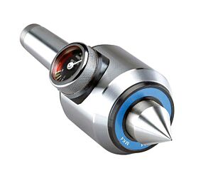
The RÖHM dragger is preloaded through hydraulic compensation. It comes with the ability to perform turning operations from a minimum diameter of 13mm up to a diameter of 64mm. The claws are supplied in steel with HRC-35 hardness.
Carton Box contents:
No. 1 pcs. Constant face driver body
No. 2 pcs. Dragger disc (Ø 12, 32)
No. 2 pcs. Centre tip (Ø 6, 16)


Mounting table and technical characteristics:
| Dimensions driving discs clamping circuit | Centre points | Approx. turning range Min-Max. | Axial load Max. |
| Ø8mm | Ø4mm | 9-16mm | 4000N |
| Ø10mm | Ø4mm | 11-20mm | 6000N |
| Ø12mm | Ø6mm | 13-24mm | 6000N |
| Ø16mm | Ø10mm | 17-32mm | 6000N |
| Ø20mm | Ø12mm | 21-40mm | 8000N |
| Ø25mm | Ø16mm | 26-50mm | 10000N |
| Ø32mm | Ø16mm | 33-64mm | 12500N |
| Ø40mm | Ø16mm | 41-80mm | 14000N |
| Ø50mm | Ø16mm | 51-100mm | 14000N |
| Ø63mm | Ø16mm | 64-126mm | 14000N |
| Ø80mm | Ø16mm | 81-160mm | 14000N |
Draggers for machining on lathes or milling machines
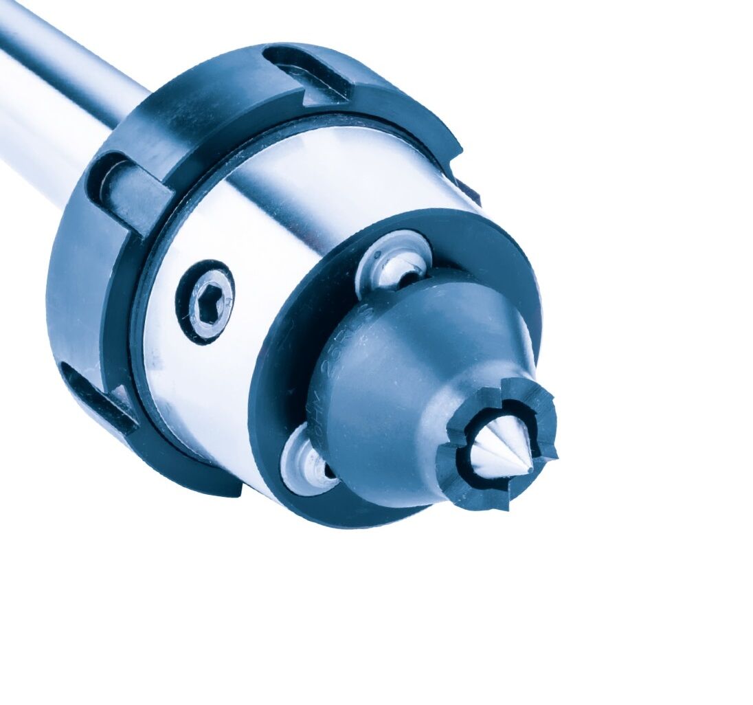
They are mainly used for milled or turned shafts. The front feed consists of a basic body, guide discs and/or drive jaws and a centre point.
Machining is performed on semi-finished workpieces, which are centred on the lathe using centring centres, so that the workpiece axis can be guided and centred during machining on the machine tools.
The drigger is mounted in the main spindle nose of the lathe. Penetrating into the plane of the workpiece at the front, the claws exert a rotary motion on the spindle, preventing it from slipping during turning. When the workpiece is clamped in the spindle, the centring tip penetrates the central point previously fixed to the workpiece, thus ensuring the exact positioning of the claws on the axes of the workpiece. The centre point inside the driver has a compression stroke, the compression force of which is applied during pre-clamping using cup springs or compression springs determined by the weight and rotation of the workpiece.
The correct Constant drive is determined by choosing the following characteristics:
- Direction of rotation of the workpiece (right or left)
- Maximum claw diameter and the maximum diameter of the workpiece to be turned
- Check of the diameter of the centre cutter to be performed on the semi-finished part to be mounted on the machine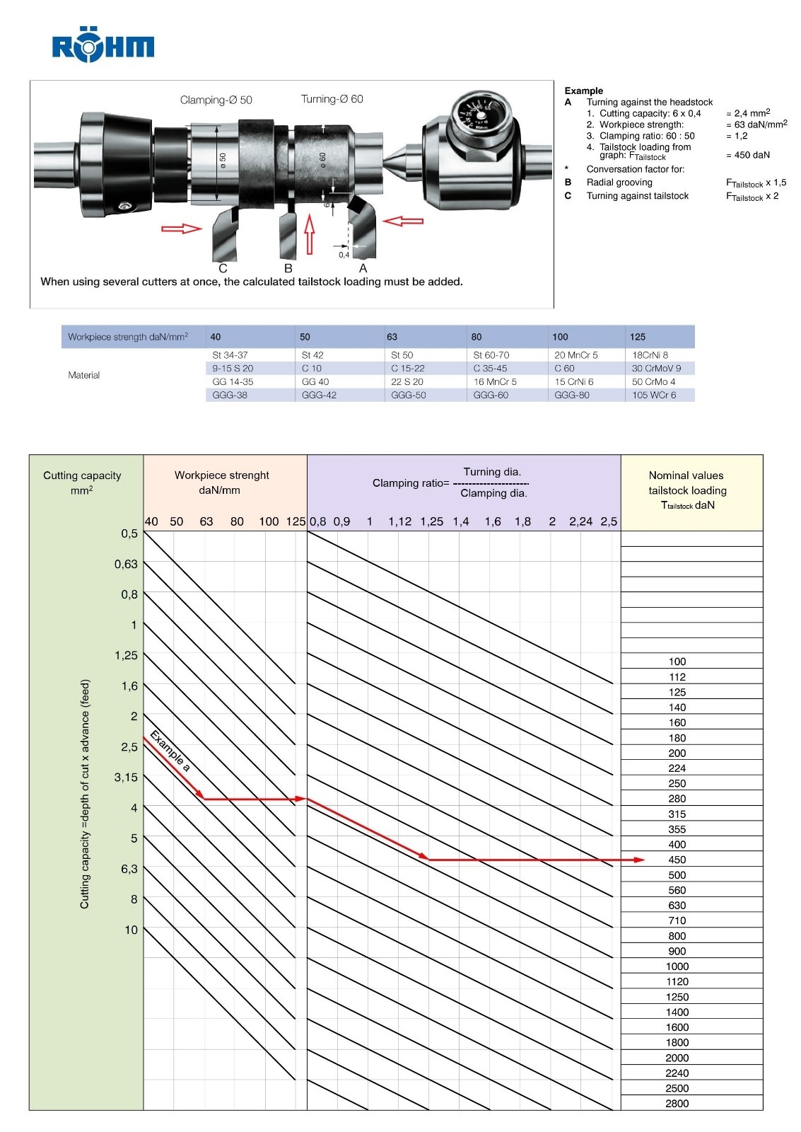 Interpretation of the Diagram for Constant Face Drives for Turning and Milling Cylindrical Parts or Shafts
The Constant Face Drive is a tool that ensures precise turning without shape errors or tolerance deviations around the rotation axis of the workpiece. Given the importance of correct adjustment, it is strongly recommended to follow these guidelines to avoid injuries, including very serious ones, during turning operations. In case of doubts, it is advisable to contact technical experts, such as the staff at Tadaah, who can provide support for the purchase and optimal use of Constant Face Drives.
The following information refers to and is valid only for perfectly intact and new Rohm products; however, it is always advisable to contact Tadaah or Rohm for further verification in any case.
Below is the necessary material for the machining processes:
- Preparation of the Raw Workpiece: The workpiece is initially machined with a facing and centering phase (creating center holes) on both sides.
- Mounting the Constant Face Drive: The Constant Face Drive can be mounted directly in the self-centering chuck or, if it has a Morse taper, it can be secured in the self-centering chuck with a suitable reduction.
- Use of the Tailstock with Dynamometer: On the opposite side of the Constant Face Drive, a tailstock equipped with a dynamometer is mounted. This tool allows you to know exactly the preload of the Constant Face Drive during the turning operation.
Preload Adjustment:
To work safely, efficiently, and precisely, while also avoiding serious injuries to personnel, it is essential to correctly adjust the preload of the Constant Face Drive's jaws. Use the data provided below to accurately calculate the preload of the Constant Face Drive with the tailstock. We attach a scale with an example, whose solution and result are highlighted by the red line.
Data needed for the calculation:
- Weight of the workpiece
- Material of the Workpiece: It is important to know the material's resistance to machining, expressed in daN per mm².
- Outer Diameter of the Constant Face Drive Disk
- Outer Diameter of the Turning
- Depth of cut and feed rate per revolution of the tool
- Tool Feed Direction: This can be from the self-centering chuck towards the outside (C) or from the tailstock towards the self-centering chuck.
Important: Depending on the tool feed direction, compensation factors must be considered, as shown in the drawing above the scale diagram:
- Compensation Factor "A": Multiplier x1
- Compensation Factor "B": Multiplier x1.5
- Compensation Factor "C": Multiplier x2
In the case of multiple operations being performed simultaneously, the sum of each result must be calculated.
- Brand:
- ROHM