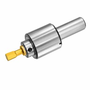
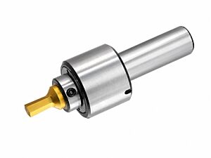
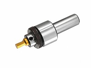
175.500 Fixed revolving broach toolholders with cylindrical shank for internal broaching, broach length 10 mm, cylindrical shank of your choice
(Incl. Tax: €218.50)
The fixed revolving broach toolholders with cylindrical shank are designed for internal broaching operations on lathes, machining centers and drilling machines, using dedicated broaches with the correct H dimension. They allow the production of internal hexagons, internal squares, slots and regular internal profiles through machine rotation and axial feed. Correct centering, proper pre-hole preparation and suitable feed selection help achieve accurate profiles, reduce broach wear and improve machining quality.

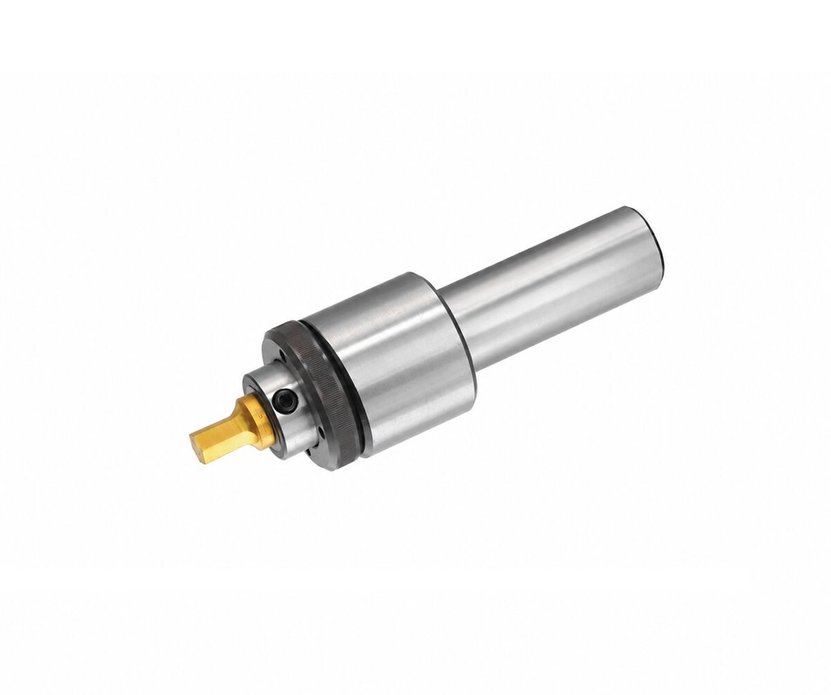
The fixed revolving broach toolholder with cylindrical shank is a broach-holding device designed for the production of internal profiles on machine tools, especially lathes, machining centers and drills prepared for precision operations. It is a technical toolholding solution intended for use with dedicated broaches in order to produce, in a controlled and repeatable way, internal hexagons, internal squares, internal rectangular profiles, keyway-type internal slots and other regular internal forms, while maintaining good geometrical accuracy and efficient machining performance.
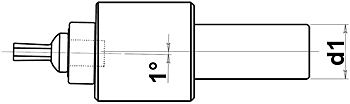
The operating principle of rotary broaching is based on a slight controlled angular offset between the axis of the broach and the axis of the broach holder body. This offset allows the broach to cut progressively rather than impacting the material fully at once, promoting smoother material removal. The rotation and axial feed provided by the machine tool reproduce inside the hole the same front profile as the broach. This system is widely appreciated because it enables internal profile generation with a compact toolholder that is easier to integrate than more complex traditional broaching systems.
From an application standpoint, the principle remains the same even when the machine kinematics change. On a lathe, the workpiece and the broach normally rotate while the body of the broach holder remains stationary. On a machining center or other suitable machine, the workpiece and broach may remain stationary while the body of the broach holder rotates. In both cases, the combination of rotary motion and axial feed generates the broaching action. This gives the system excellent flexibility for both conventional workshops and advanced CNC environments.
These toolholders are intended for internal broaching and must be used with specific broaches having the correct H dimension, as indicated in the technical data. This is essential because correct matching between holder and broach directly affects alignment, stability, profile finish and the service life of the internal components of the broach holder. A non-compatible broach, or one with geometry inconsistent with the required H value, may cause abnormal wear, tool seizure, oversize or undersize profiles, or irregular machining.
The toolholder can be used for internal hexagons, internal squares, internal rectangular forms, keyway-type slots, splined or slotted internal forms and other compatible internal profiles. In industrial practice it is useful for mechanical parts, bushes, rings, shafts, drive components, coupling elements and precision components where a repeatable internal form must be produced without resorting to slower or more complex multi-step processes.
Broaches used with this system are generally manufactured from through-hardened high-hardness tool steel and are suitable for machining steel, brass, aluminum, cast iron and other materials, with possible availability of TiN or BLK coated versions to improve tool life, wear resistance and sliding behavior. The choice between a standard and a coated broach depends on the material being machined, production volume, required finish and the overall machining strategy.
As for operating parameters, the recommended spindle speed is generally between 1000 and 2500 rpm. Speed has a moderate influence on the functionality of the system, while feed rate is much more critical and must be selected according to the material, the amount of stock to be removed, machine rigidity, workholding stability and pre-hole quality. A rigid and well-aligned machine normally allows more efficient and stable conditions, whereas weak clamping or lower rigidity requires more conservative settings.
The initial contact phase between broach and workpiece is particularly delicate. At the beginning, the broach tends to rub before reaching full engagement, and wear may be higher in this stage. For that reason, when machine setup allows it, it is advisable to start with low rotational speed and relatively fast feed for about 0.5 mm, so that the tool reaches full cutting engagement quickly. Once stable contact has been achieved, the parameters can be increased to the target operating level. This practical method can help improve broach life and profile quality.
Correct pre-hole preparation is essential in internal broaching. The initial hole should not be selected randomly, but must be sized according to the profile to be produced and the material being machined. In general, a pre-hole slightly larger than the minimum profile size helps reduce feed force, lower the load on the broach, improve cut quality and reduce wear. This is especially important for internal hexagons, internal squares, operations in harder materials or larger internal profiles, where the amount of material to be removed strongly affects process stability.
Another key factor is the centering of the broach relative to the workpiece. Poor alignment may damage the surface finish, increase wear on the broach and on the toolholder bearings, and generate the so-called spiral effect, meaning a helical broached form instead of a straight and regular one. To reduce this risk, it is important to verify machine alignment, clamping rigidity, absence of abnormal play, correct bearing condition and overall alignment between tool and hole. Where recommended by the manufacturer or the application, the use of a driving plate can also help ensure proper system behavior.
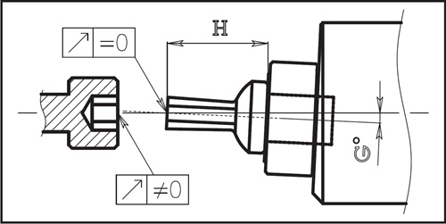
Among the most common shop-floor issues are tool sticking, out-of-size internal forms, spiral broaching and non-uniform surface finish. In such cases, the first points to check are the pre-hole diameter, broach geometry, bearing condition, machine rigidity, workholding quality and feed setting. In many cases, the root cause is not the broach holder itself, but the interaction between material, initial hole, machining parameters and setup alignment.
From a design standpoint, the broach holder is available with cylindrical shank in several sizes to match different machines and toolholding systems. The available versions cover d diameters from 8 mm to 22 mm, with I = 34 mm, L = 35 mm or 46 mm depending on version, D = 22 mm, F = 5 mm and H = 10 mm. This range allows the user to select the most suitable shank while maintaining the essential requirement of using broaches compatible with the specified H dimension.
For machine shops, tool setters, turners, CNC programmers, maintenance technicians and production managers, this broach holder is a reliable technical solution for precision internal broaching with compact equipment, good repeatability and broad application flexibility. When correctly selected according to the machine, broach, pre-hole and machining parameters, it allows regular internal profiles to be produced while limiting tool wear and improving process efficiency.
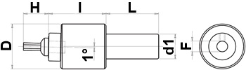
Cylindrical fitting - Technical dimensions
| d1 (mm) | l (mm) | L (mm) | D (mm) | F (mm) | H (mm) |
|---|---|---|---|---|---|
| 8 | 34 | 35 | 22 | 5 | 10 |
| 10 | 34 | 35 | 22 | 5 | 10 |
| 12 | 34 | 35 | 22 | 5 | 10 |
| 14 | 34 | 35 | 22 | 5 | 10 |
| 15.875 | 34 | 35 | 22 | 5 | 10 |
| 16 | 34 | 35 | 22 | 5 | 10 |
| 19.05 | 34 | 46 | 22 | 5 | 10 |
| 20 | 34 | 46 | 22 | 5 | 10 |
| 22 | 34 | 46 | 22 | 5 | 10 |
Feed per revolution - Materials and geometries
| Material to be worked | Hexagons < 14 mm | Hexagons > 14 mm | Squares < 12 mm | Squares > 12 mm |
|---|---|---|---|---|
| Magnetic soft steel - Structural steel, case carburizing steel, free cutting steel (AVP) Rm < 700 N/mm² |
0.10 | 0.08 | 0.06 | 0.04 |
| Plain carbon steel - Alloyed steel - heat-treatable steel, steel castings Rm 700 ÷ 850 N/mm² |
0.08 | 0.06 | 0.05 | 0.03 |
| Alloyed steel - heat-treatable steel - nitriding steel - steel casting Rm 850 ÷ 1200 N/mm² |
0.06 | 0.03 | 0.03 | 0.02 |
| Alloyed steel - high strength steel Rm 1200 ÷ 1400 N/mm² |
0.02 | 0.02 | 0.02 | 0.02 |
| Free machining stainless steel - austenitic stainless steel Rm < 850 N/mm² |
0.08 | 0.06 | 0.04 | 0.03 |
| Ferritic - ferritic + austenitic - martensitic stainless steel Rm > 850 N/mm² |
0.04 | 0.03 | 0.03 | 0.02 |
| Lamellar grey cast iron Rm < 600 N/mm² |
0.11 | 0.08 | 0.07 | 0.04 |
| Lamellar grey cast iron - nodular cast iron - malleable cast iron Rm 600 ÷ 1000 N/mm² |
0.07 | 0.05 | 0.04 | 0.03 |
| Aluminium long chipping Rm < 500 N/mm² Si < 10% |
0.14 | 0.10 | 0.10 | 0.08 |
| Aluminium short chipping Rm > 500 N/mm² Si > 10% |
0.10 | 0.08 | 0.08 | 0.06 |
| Copper - soft brass long chipping Rm < 700 N/mm² |
0.12 | 0.09 | 0.10 | 0.08 |
| Copper - hard brass short chipping Rm < 700 N/mm² |
0.08 | 0.06 | 0.07 | 0.05 |
| Titanium unalloyed Rm < 700 N/mm² |
0.06 | 0.03 | 0.03 | 0.02 |
| Titanium alloys Rm > 700 N/mm² |
0.03 | 0.02 | 0.02 | 0.02 |
Preparation for broaching / drilling - Internal broaching
| Condition | Hexagonal seats | Square seats |
|---|---|---|
| < 14 mm and similar | Oversized drilling approx. 1% - 3% | Oversized drilling approx. 3% - 7% |
| > 14 mm and hard materials | Oversized drilling approx. 5% | Oversized drilling approx. 10% |
| > 21 mm | Oversized drilling approx. 5% - 10% | — |
| > 17 mm | — | Oversized drilling approx. 15% |
- Brand:
- TADAAH
- Typology:
- Internal broach