08.29.100 Standard radial disc cam for Gildemeister AS16, AS20, GS20, GM20, GM20AC multi-spindle lathes.
(Incl. Tax: €142.74)
Gildemeister DMG Mori radial cams for GM20 multi-spindle automatic lathes, available in different configurations according to mounting position, nominal stroke h and working arc. They convert camshaft rotation into controlled radial-slide movement, ensuring accurate cycle timing and repeatability. The adjustable lever system, with ratios of 0.5, 0.625, 0.75, 0.875 and 1, allows the effective stroke to be adapted to the machining operation. Standard versions are available for position 1, positions 2-6 and long-stroke applications in position 2.

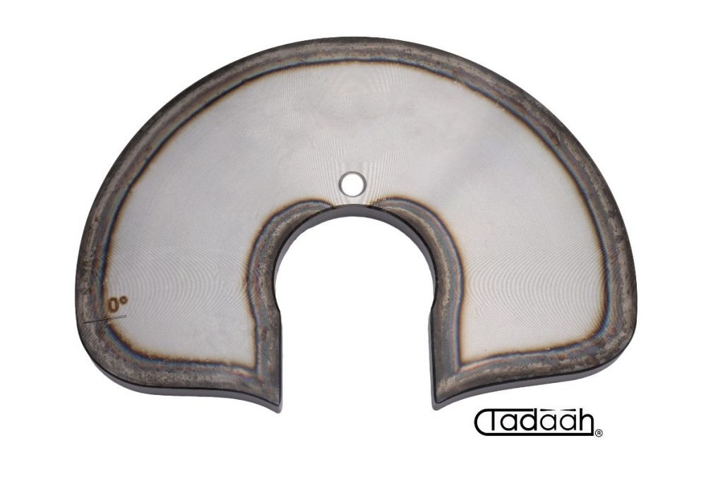


The Gildemeister DMG Mori radial cams for the GM20 multi-spindle automatic lathe are mechanical control components designed to determine, synchronise and repeat the movement of the radial slides throughout the machining cycle. The configurable family includes standard cams for position 1, cams intended for radial positions 2 through 6, and dedicated long-stroke versions for position 2. Depending on the machine configuration, original documentation and installed tooling, these geometries may also be used on machines belonging to the AS20, GS20 and GM20AC series.
The cam converts the continuous rotation of the camshaft into a controlled linear movement of the lever and radial slide. Its profile determines when the cutting tool approaches the workpiece, how progressively it reaches the working position, how long it remains engaged and how it returns to its initial position. This mechanical system coordinates several operations across the different spindles, providing short cycle times and high repeatability in large-volume production.
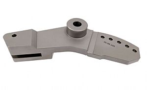
The image shows the lever-ratio adjustment system with five positions marked 0.5, 0.625, 0.750, 0.875 and 1. Selecting a different hole changes the kinematic ratio between the cam, lever and radial slide and therefore changes the travel transmitted to the tool. The theoretical effective stroke is calculated by multiplying the nominal cam stroke h by the selected ratio. A cam with a nominal stroke h of 3 mm, for example, theoretically provides 1.5 mm at ratio 0.5, 1.875 mm at 0.625, 2.25 mm at 0.75, 2.625 mm at 0.875 and the full 3 mm at ratio 1.
The lever ratio must not be regarded simply as a depth-of-cut adjustment. Changing the ratio also changes slide movement, tool speed, acceleration and the loads transmitted through the mechanism. A lower ratio reduces the travel, whereas ratio 1 uses the full nominal stroke. The correct setting must therefore be selected according to the workpiece material, diameter, depth of cut, tool geometry, toolholder rigidity, camshaft speed and available cycle time.
Because this component is not a measuring instrument, resolution is not expressed as a metrological reading value. In this application, functional resolution means the discrete adjustment range provided by the five lever ratios. Final tool positioning must be completed through the toolholder and slide adjustments, with the cutting edge correctly aligned with the spindle centreline. The cam should not be used to compensate for incorrect tool height, machine misalignment or excessive mechanical backlash.
The position 1 group includes standard cams with a working arc of 165° and nominal strokes h of 1.5, 3, 6 and 12 mm. Available references are 08.29.117 for h 1.5 mm, 08.29.105 for h 3 mm, 08.29.106 for h 6 mm, and 08.29.107 or 16.29.301 for h 12 mm. The two 12 mm references must be selected by comparing the existing component reference and the machine documentation, since identical nominal values do not automatically guarantee interchangeability of all construction details. The active versions in this group have a documented rise angle of 45°, return angle of 48° and dwell angle of 12°.
Reference 08.29.111 is also available for position 1, with stroke h specified as 0 mm and a working arc of 147°. This version does not generate an active radial working stroke and is used when the machine sequence requires the slide to remain in a controlled position without a commanded working movement. Selecting a different lever hole does not create an effective stroke when the nominal h value is zero.
The standard cams for positions 2 through 6 have a working arc of 198°. The available references are 08.29.118 for h 1.5 mm, 08.29.101 for h 3 mm, 08.29.102 for h 6 mm and 08.29.103 for h 12 mm. Reference 08.29.104 is the zero-stroke version. These cams must not be installed in radial position 1 because their geometry may collide with the bar stop. Installation must also comply with the specified 33° orientation, followed by a complete timing and clearance check on the machine.
For machining operations requiring extended movement in radial position 2, the family includes long-stroke references 08.29.109 with h 3 mm and 08.29.110 with h 6 mm. Both have a 198° working arc, a 48° rise angle, a 51° return angle and a 12° dwell angle. They are particularly suitable for configurations using prismatic tools, shaving tools or tooling requiring a movement profile adapted to longer travel. These versions also require the 33° mounting orientation and must not be used in position 1.
The stroke h is the nominal movement associated with the cam profile when the lever ratio is set to 1. It does not directly correspond to the cutting depth on the workpiece diameter because the actual result also depends on the selected lever ratio, lever geometry, pin position, slide adjustment and toolholder orientation. The effective stroke must therefore be measured directly on the machine before production. A dial indicator can be placed against the radial slide while the camshaft is rotated manually through a complete cycle to verify minimum position, maximum travel, return movement and any residual play.
A critical parameter is the cam profile radius. The reference data specifies a construction range from R min 50.5 mm to R max 90 mm. These values refer to the functional profile radii and not to the overall dimensions of the component. An incorrect minimum radius can cause the lever to interfere with the cam groove or mounting area, resulting in impact, restricted movement, seizure, accelerated wear or damage to pins and contact surfaces.
Machining precision does not depend on the cam alone. Even with a geometrically correct cam profile, the actual stroke can vary because of lever-pin clearance, ovalised holes, roller or track wear, incorrect gib adjustment, radial-slide backlash, worn spindle bearings, toolholder deflection or inadequate lubrication. These conditions can cause delayed motion reversal, differences between approach and return, vibration, surface marks and dimensional variation between consecutive parts.
Quality inspection should include the cam profile, minimum and maximum radii, hole positions, concentricity relative to the mounting bore, flatness of the supporting surfaces and the absence of burrs or deformation. Profile-form errors may be evaluated using a dial indicator, optical profile projector, optical measuring system or coordinate measuring machine, comparing the results with the original drawing or a known unworn sample. Local polishing, scoring, pitting or irregular contact marks may indicate incorrect contact or a roller that is not rotating freely.
For optimum performance, check that the roller rotates freely, lubricate the specified points, reduce excessive clearance without restricting slide movement and verify the cutting-edge height relative to the spindle centreline. After installation, rotate the machine manually through a complete cycle without a workpiece and with the tool in a safe position. Confirm clearance from the bar stop, complete slide return, distance from adjacent tools and correct timing with all other operations.
Variant selection should begin with the reference of the original cam, followed by the radial position, required stroke and working arc. The lever ratio and final tool adjustment can then be defined. Replacing a worn cam with the correct version helps restore smooth movement, dimensional stability, surface quality and cycle repeatability while reducing unexpected stoppages, tool breakage and rejected components.
Radial slide strokes with standard cams for GM 20
| Cam drawing no. | Working arc | Rise angle | Return angle | Dwell angle | Rapid lift H | Working stroke h | Lever ratios and corresponding strokes | Construction from R min to R max R min 50,5 – R max 90 |
|||||||||
|---|---|---|---|---|---|---|---|---|---|---|---|---|---|---|---|---|---|
| 0,5 | 0,625 | 0,75 | 0,875 | 1 | |||||||||||||
| H | h | H | h | H | h | H | h | H | h | ||||||||
| 08.29.105 | 165° | 45° | 48° | 6° | 25 | 3 | 12,5 | 1,5 | 15,6 | 1,87 | 18,7 | 2,25 | 21,8 | 2,6 | 25 | 3 | Standard cams Pos. 1 |
| 08.29.106 | 165° | 45° | 48° | 6° | 25 | 6 | 12,5 | 3 | 15,6 | 3,75 | 18,7 | 4,5 | 21,8 | 5,25 | 25 | 6 | |
| 08.29.107 | 165° | 45° | 48° | 6° | 25 | 12 | 12,5 | 6 | 15,6 | 7,5 | 18,7 | 9 | 21,8 | 10,5 | 25 | 12 | |
| 08.29.117 | 165° | 45° | 48° | 6° | 26,5 | 1,5 | 13,25 | 0,75 | 16,56 | 0,94 | 19,87 | 1,12 | 23,2 | 1,31 | 26,5 | 1,5 | |
| 16.29.301 | 165° | 45° | 48° | 6° | 30 | 12 | 15 | 6 | 18,75 | 7,5 | 22,5 | 9 | 26,2 | 10,5 | 30 | 12 | |
| 08.29.111 | 147° | 45° | 48° | 147° | 36 | – | 18 | – | 22,5 | – | 27 | – | 31,5 | – | 36 | – | |
| 08.29.101 | 198° | 45° | 48° | 6° | 25 | 3 | 12,5 | 1,5 | 15,6 | 1,87 | 18,7 | 2,25 | 21,8 | 2,6 | 25 | 3 | Standard cams Pos. 2–3–4–5–6 |
| 08.29.102 | 198° | 45° | 48° | 6° | 25 | 6 | 12,5 | 3 | 15,6 | 3,75 | 18,7 | 4,5 | 21,8 | 5,25 | 25 | 6 | |
| 08.29.103 | 198° | 45° | 48° | 6° | 25 | 12 | 12,5 | 6 | 15,6 | 7,5 | 18,7 | 9 | 21,8 | 10,5 | 25 | 12 | |
| 08.29.118 | 198° | 45° | 48° | 6° | 26,5 | 1,5 | 13,25 | 0,75 | 16,56 | 0,94 | 19,87 | 1,12 | 23,2 | 1,31 | 26,5 | 1,5 | |
| 08.29.104 | 198° | 45° | 48° | 198° | 36 | – | 18 | – | 22,5 | – | 27 | – | 31,5 | – | 36 | – | |
| 08.29.109 | 198° | 48° | 51° | 6° | 36 | 3 | 18 | 1,5 | 22,5 | 1,87 | 27 | 2,25 | 31,5 | 2,63 | 36 | 3 | Standard cams for long strokes Pos. 2 – prismatic tools/shaving tools |
| 08.29.110 | 198° | 48° | 51° | 6° | 36 | 6 | 18 | 3 | 22,5 | 3,75 | 27 | 4,5 | 31,5 | 5,25 | 36 | 6 | |
- Brand:
- GILDEMEISTER - DMG MORI
- Typology:
- Standard Radial
- Machine Type:
- AS16, AS20, GM20, GM20AC, GS20