16.29.200 Standard cams for axial slides positions 1-2-4-5 for Gildemeister DMG-Mori AS16, AS20, GS20, GM20, GM20AC multi-spindle lathes
In stock
Only %1 left
SKU
TD-1629200
As low as
€117.00
(Incl. Tax: €142.74)
(Incl. Tax: €142.74)
The configurable 16.29.200 standard cams control the longitudinal movement of axial slides in positions 1-2-4-5 on Gildemeister DMG-Mori multi-spindle lathes. The family includes position 1 cams with a 156° working arc and position 2-4-5 cams with a 189° working arc, with nominal working stroke h from 2.5 to 40 mm at lever ratio 1 and continuous ratio adjustment from 0.8 to 1.6. Used together with the radial cam, they enable synchronised cylindrical turning, shoulders, reliefs and longitudinal passes. Correct installation, stroke measurement and backlash inspection support dimensional accuracy, uniform feed and consistent workpiece geometry.

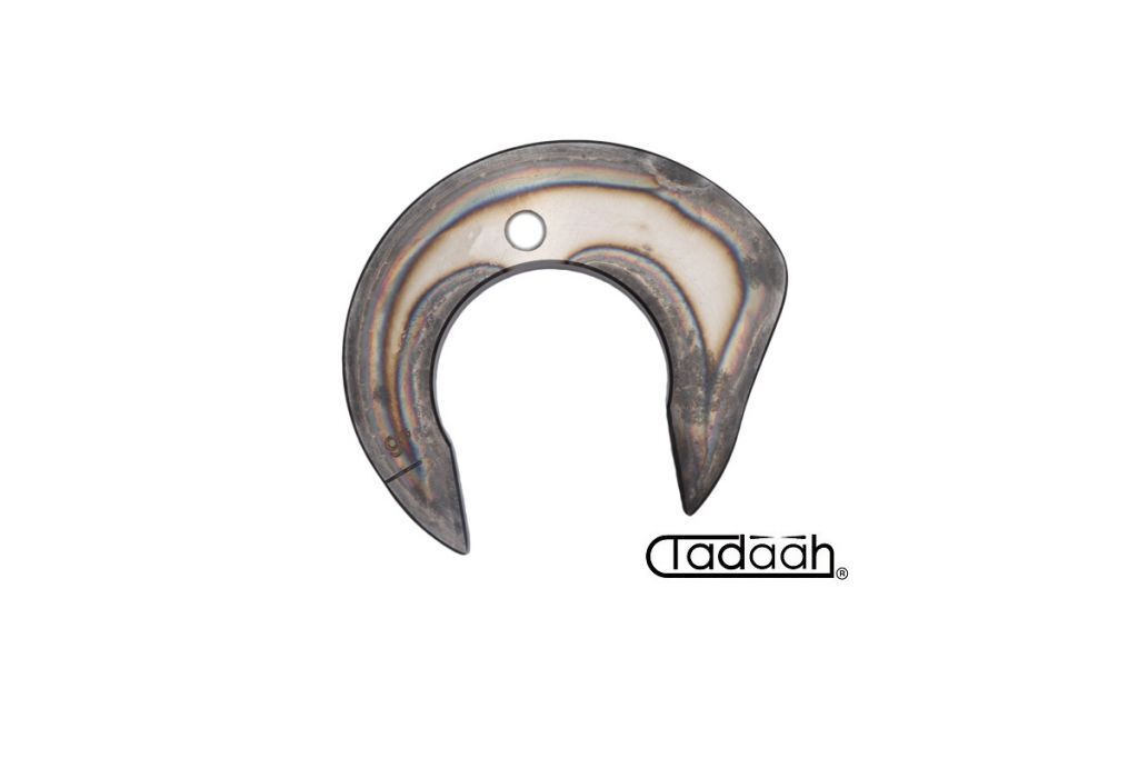
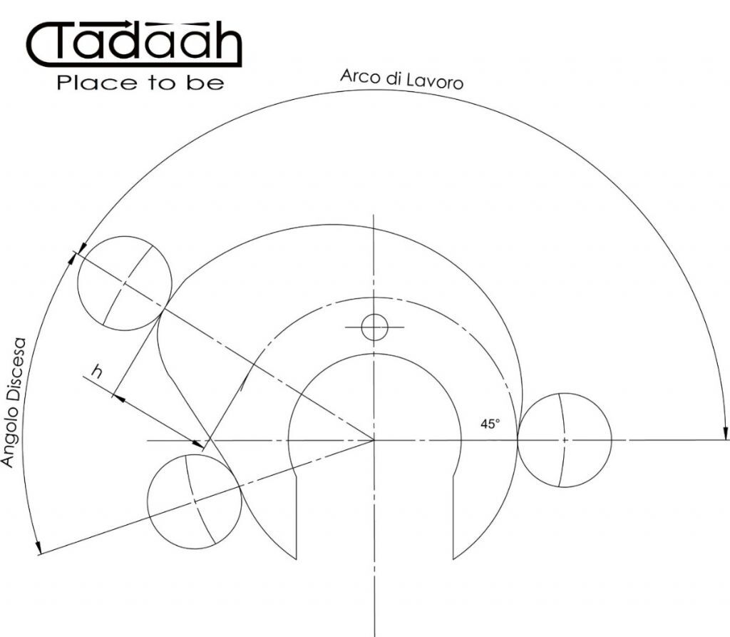
The configurable code 16.29.200 groups the family of standard axial cams used to control the longitudinal movement of cross slides in positions 1-2-4-5 on Gildemeister DMG-Mori AS16, AS20, GS20, GM20 and GM20AC automatic multi-spindle lathes. The reference kinematic values are taken from the GM20 standard cam table. Before installation on a different model or version, the machine configuration, installed slide unit, lever system, roller diameter, available clearances and cycle timing must be checked. The configurable product helps identify the correct simple cam according to axial position, required working stroke h and available working arc. Axial cams were developed to convert the continuous rotation of the camshaft into a controlled and repeatable longitudinal slide movement. During axial turning they normally work together with a radial cam. The radial cam determines tool approach, depth of cut and the diametral dimension, while the axial cam produces movement parallel to the workpiece axis. Synchronisation of the two profiles enables cylindrical turning, longitudinal sections, shoulders, reliefs and finishing passes on turned components. The mechanical cam solution keeps the motion law linked to machine rotation and supports fast, robust and repeatable cycles in continuous production. The family is divided into two mounting groups. For axial position 1 the available cams are 16.29.207 with working stroke h 2.5 mm, 16.29.206 with 5 mm, 16.29.202 with 10 mm, 16.29.205 with 14 mm, 16.29.201 with 20 mm, 16.29.204 with 28 mm and 16.29.203 with 40 mm. These versions have a 156° working arc and must be mounted in the specified position at a 45° orientation, respecting the timing reference and checking that no binding occurs throughout the complete rotation. For axial positions 2-4-5 the available cams are 08.29.607 with working stroke h 2.5 mm, 08.29.606 with 5 mm, 08.29.602 with 10 mm, 08.29.605 with 14 mm, 08.29.601 with 20 mm, 08.29.604 with 28 mm and 08.29.603 with 40 mm. These cams have a 189° working arc and must not be fitted in position 1 because their envelope and movement may interfere with the bar stop. All versions have a 15° rise angle. The fall angle changes with the working stroke h and is 15° for 2.5 mm, 30° for 5 mm, 33° for 10 mm, 36° for 14 mm, 39° for 20 mm and 45° for the 28 and 40 mm strokes. The dwell angle is 6°. The stated construction range is from minimum radius 50.5 mm to maximum radius 91.5 mm. These values must be compared with the available space, roller position and lever geometry before compatibility is confirmed. The working stroke h stated for each cam refers to lever ratio 1. Moving the index provides continuous lever-ratio adjustment from 0.8 to 1.6 and proportionally changes the actual slide travel. The indicative range is 2 to 4 mm for the nominal 2.5 mm cam, 4 to 8 mm for the 5 mm cam, 8 to 16 mm for the 10 mm cam, 11.2 to 22.4 mm for the 14 mm cam, 16 to 32 mm for the 20 mm cam, 22.4 to 44.8 mm for the 28 mm cam and 32 to 64 mm for the 40 mm cam. Table reference settings are 0.8 - 1 - 1.1 - 1.2 - 1.3 - 1.4 - 1.5 - 1.6. Because adjustment is mechanical and continuous, practical resolution is not a fixed digital increment. It depends on index readability, clamping accuracy, lever rigidity, roller diameter and backlash in the kinematic chain. Correct selection starts from the effective turning length and adds tool approach, stock allowance, possible regrinding compensation, safety clearance and the travel needed for complete slide return before drum indexing. A cam with insufficient stroke cannot reach the specified longitudinal dimension. Excessive stroke creates unnecessary movement, can increase cycle time and may bring the tool into an unintended area. The working arc must also be coordinated with camshaft speed, spindle revolutions and the required feed on the workpiece. For the same stroke, a larger arc distributes the movement over a longer phase and reduces instantaneous feed, while a shorter arc creates a faster movement and requires closer attention to vibration, cutting-edge wear and surface quality. Installation must be carried out with the machine stopped, isolated and made safe. Before final tightening, clean the mounting surfaces, verify the cam code, identify the correct position and check angular orientation. The roller must contact the profile correctly without running on an edge and must rotate freely. The lever and slide must complete the entire travel without impact, binding or interference. Position 1 requires the 45° mounting orientation. Positions 2-4-5 require a clearance check around the bar stop and nearby components. After installation, set the lever ratio, move the machine to the start of stroke and measure the actual displacement. Slide travel can be checked with a dial or test indicator aligned parallel to the direction of movement and zeroed against a stable reference. Indicators, height gauges, depth micrometers, callipers, gauges and approved sample parts can be used to verify the starting position, cutting-edge height and final dimension. The first test must be carried out by manually rotating the shaft or using a very low speed. During the test, inspect the start of feed, maximum position, return movement, tool clearance and absence of collisions. Repeat the measurement after final tightening and verify the dimension again after the initial machine warm-up because settling, lubrication and thermal expansion can slightly change the result. Final accuracy depends not only on the nominal cam profile but on the complete chain consisting of cam, roller, pin, lever, bushes, bearings, slide, toolholder and cutting tool. Profile wear, eccentricity, form errors, an out-of-round roller, pin clearance, worn bushes, loose bearings, lever deflection, incorrectly adjusted ways or insufficient clamping can cause stroke variation and non-uniform feed. On the workpiece these defects can appear as errors in length, shoulder position, cylindricity, straightness, unwanted taper, concentricity and surface roughness. Incorrect cutting-edge height relative to the workpiece centre can also alter geometry and increase cutting load. To optimise the cycle, coordinate the axial cam with the radial cam, spindle speed, depth of cut, workpiece material, cutting-edge geometry, nose radius, coolant supply and chip evacuation. Excessive feed can produce vibration, scoring and rapid tool deterioration. Insufficient feed can reduce output and encourage built-up edge. Setup must be confirmed by dimensional inspection of the first components and by checking the surface finish. Preventive maintenance includes regular cleaning and lubrication, inspection of the profile, roller and pivot points, verification of transmission backlash and adjustment of the slideways. A setup sheet should record the selected cam code, position, lever ratio, measured stroke, matching radial cam, tool and achieved dimensions. This documentation reduces setup time and assists fault diagnosis during corrective maintenance. The configurable product is intended for multi-spindle setup technicians, machine operators, cycle-planning departments, machine-tool builders and rebuilders, maintenance teams, quality-control departments, automotive manufacturers and precision-machining companies. Tadaah presents this family as a technical selection and purchasing support tool. Before ordering, compare the existing cam code, mounting position, required working stroke h, working arc, lever ratio and actual machine clearances.
Axial slide strokes with standard cams for GM 20
| Cam drawing no. | Working arc | Return angle | Dwell angle | Working stroke h | Lever ratios and corresponding strokes | Construction from R min to R max R min 50,5 R max 91,5 |
|||||||
|---|---|---|---|---|---|---|---|---|---|---|---|---|---|
| 0,8 | 1 | 1,1 | 1,2 | 1,3 | 1,4 | 1,5 | 1,6 | ||||||
| h | h | h | h | h | h | h | h | ||||||
| 16.29.207 | 156° | 15° | 6° | 2,5 | 2 | 2,5 | 2,75 | 3 | 3,25 | 3,5 | 3,75 | 4 | Standard cams Pos. 1 |
| 16.29.206 | 156° | 30° | 6° | 5 | 4 | 5 | 5,5 | 6 | 6,5 | 7 | 7,5 | 8 | |
| 16.29.202 | 156° | 33° | 6° | 10 | 8 | 10 | 11 | 12 | 13 | 14 | 15 | 16 | |
| 16.29.205 | 156° | 36° | 6° | 14 | 11,2 | 14 | 15,4 | 16,8 | 18,2 | 19,6 | 21 | 22,4 | |
| 16.29.201 | 156° | 39° | 6° | 20 | 16 | 20 | 22 | 24 | 26 | 28 | 30 | 32 | |
| 16.29.204 | 156° | 45° | 6° | 28 | 22,4 | 28 | 30,8 | 33,6 | 36,4 | 39,2 | 42 | 44,8 | |
| 16.29.203 | 156° | 45° | 6° | 40 | 32 | 40 | 44 | 48 | 52 | 56 | 60 | 64 | |
| 08.29.607 | 189° | 15° | 6° | 2,5 | 2 | 2,5 | 2,75 | 3 | 3,25 | 3,5 | 3,75 | 4 | Standard cams Pos. 2–4–5 |
| 08.29.606 | 189° | 30° | 6° | 5 | 4 | 5 | 5,5 | 6 | 6,5 | 7 | 7,5 | 8 | |
| 08.29.602 | 189° | 33° | 6° | 10 | 8 | 10 | 11 | 12 | 13 | 14 | 15 | 16 | |
| 08.29.605 | 189° | 36° | 6° | 14 | 11,2 | 14 | 15,4 | 16,8 | 18,2 | 19,6 | 21 | 22,4 | |
| 08.29.601 | 189° | 39° | 6° | 20 | 16 | 20 | 22 | 24 | 26 | 28 | 30 | 32 | |
| 08.29.604 | 189° | 45° | 6° | 28 | 22,4 | 28 | 30,8 | 33,6 | 36,4 | 39,2 | 42 | 44,8 | |
| 08.29.603 | 189° | 45° | 6° | 40 | 32 | 40 | 44 | 48 | 52 | 56 | 60 | 64 | |
- Brand:
- GILDEMEISTER - DMG MORI
- Typology:
- Standard Longitudinal Cam
- Machine Type:
- AS16, AS20, GM20, GM20AC, GS20