08.29.200 Standard front spindle cam for Gildemeister-DMG Mori AS20, GS20, GM20, GM20AC multi-spindle lathes
In stock
Only %1 left
SKU
TD-0829200
As low as
€117.00
(Incl. Tax: €142.74)
(Incl. Tax: €142.74)
The 08.29.200 is the configurable standard front spindle cam for Gildemeister-DMG Mori AS20, GS20, GM20 and GM20AC multi-spindle lathes. The family includes versions for front positions 2-3-4-5-6 with a nominal working stroke h from 0 to 27 mm, a 189° working arc and a 25 mm rapid stroke H at lever ratio 1. Its profile synchronises drilling, threading, tailstock support and other coaxial operations. Selecting the correct version and lever ratio allows stroke, feed and contact time to be matched to the machining cycle while controlling transmission backlash, accuracy and safe tool withdrawal.

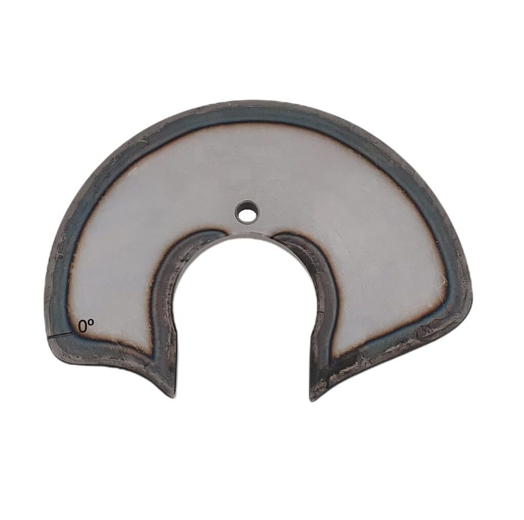

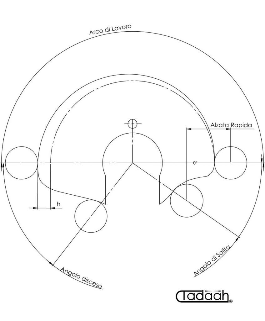
The 08.29.200 identifies the configurable product for the family of standard front spindle cams used to control front spindles on Gildemeister-DMG Mori AS20, GS20, GM20 and GM20AC automatic multi-spindle lathes. The reference kinematic data are taken from the GM20 standard cam table, while actual compatibility must be checked against the machine version, the installed front unit and the tooling configuration. The cam converts the continuous rotation of the camshaft into a synchronised, repeatable and mechanically defined axial movement of the front spindle. This solution coordinates the tool movement with the other phases of the cycle without requiring an electronic axis, which is especially useful in repetitive turned-parts production where output, robustness and consistent cycle time are priorities. The 08.29.200 family is intended for front positions 2-3-4-5-6. It must not be used in front position 1, which requires a dedicated cam group with a different orientation and specific clearance checks around the bar stop. The profile can drive fixed or rotating front spindles and can be used for drilling, tapping, die threading, supporting the workpiece with a tailstock centre, rotary drilling with small-diameter tools, light reaming and other operations coaxial with the workpiece axis. Selection must always take account of tool length, required depth, workpiece material, spindle speed, chip evacuation capability and the clearance needed for complete tool withdrawal before drum indexing. The configurable product combines standard versions with a 189° working arc, 45° rise angle, 42° fall angle, 25 mm rapid stroke H at lever ratio 1 and a construction range from minimum radius 50.5 mm to maximum radius 102.5 mm. The available options differ by nominal working stroke h at lever ratio 1: code 08.29.205 with h 0 mm, code 08.29.201 with h 2.5 mm, code 08.29.202 with h 5 mm, code 08.29.203 with h 10 mm, code 08.29.204 with h 20 mm and code 16.29.408 with h 27 mm. The h 0 mm version has a 189° dwell angle, while the versions with a working stroke h from 2.5 to 27 mm use the corrected 6° dwell angle. The working stroke h is the useful feed phase assigned to the machining operation, whereas the rapid stroke H provides approach and withdrawal of the front spindle. The lever ratio is continuously adjustable and the reference settings 0.8 - 1 - 1.2 - 1.4 - 1.6 proportionally change both rapid stroke H and working stroke h. The five ratios correspond to rapid strokes H of 20 - 25 - 30 - 35 - 40 mm. For the h 2.5 mm version the corresponding working strokes are 2 - 2.5 - 3 - 3.5 - 4 mm. For the h 5 mm version they are 4 - 5 - 6 - 7 - 8 mm. For the h 10 mm version they are 8 - 10 - 12 - 14 - 16 mm. For the h 20 mm version they are 16 - 20 - 24 - 28 - 32 mm. For the h 27 mm version they are 21.6 - 27 - 32.4 - 37.8 - 43.2 mm. The h 0 mm version retains zero working stroke at every ratio. Since adjustment is continuous, intermediate values can be set between the reference marks, but practical resolution is not a fixed digital value. It depends on index readability, locking accuracy, lever rigidity, transmission backlash and the measurement method used. Correct selection starts from the effective machining depth and adds the allowance required for tool entry, safety, cutting-edge geometry, possible regrinding compensation and withdrawal. Excessive stroke lengthens the cycle and can increase impact, vibration and wear. Insufficient stroke can prevent the target dimension from being reached, leave a thread incomplete or fail to provide complete tool clearance. For deep drilling or sensitive tools, the profile should provide a feed compatible with drill diameter and workpiece material, while avoiding excessive acceleration during the rise phase. For taps and dies, stroke, spindle speed and toolholder kinematics must be coordinated to avoid axial overload or unsynchronised reversal. Installation must be carried out with the machine stopped and safely isolated. Check the angular reference, cam clamping, roller contact and free rotation of the complete system. After installation, set the lever-ratio index, position the front spindle and measure the actual stroke. Rapid stroke H and working stroke h can be checked with a dial or test indicator aligned with the direction of movement and zeroed against a stable reference. Final heights and depths can be verified with indicators, depth micrometers, gauges, callipers and approved sample parts. The first test must be performed by hand rotation or at reduced speed while following the entire cam profile and confirming that the drill, tap, die, tailstock centre or rotating tool is completely clear of the workpiece before indexing. The measurement should be repeated after final tightening and after the initial machine warm-up because settling and thermal expansion may slightly change the result. Achievable accuracy depends on the geometric quality of the profile and on the complete kinematic chain. Roller wear, cam eccentricity, profile-form errors, front-spindle misalignment, clearance in bushes and pins, excessive bearing play, toolholder deflection or inadequate clamping can cause stroke variation, non-uniform feed and vibration. On the component, these conditions can appear as errors in depth, coaxiality, cylindricity, straightness, concentricity, surface finish and hole or thread geometry. Quality control should therefore compare theoretical and measured stroke and inspect the workpiece with suitable instruments, separating cam-related errors from those caused by the tool, spindle, material or cutting parameters. For best performance, keep the contact surfaces clean and lubricated, periodically inspect the roller, pin, lever, bushes, bearings and locking devices, remove abnormal backlash and record the settings that produced a stable cycle. Preventive replacement of worn components reduces dimensional variation and unplanned downtime. A setup sheet recording cam code, lever ratio, measured stroke, tool, working dimension and front position makes the cycle easier to restore and improves both preventive and corrective maintenance. This family is intended for multi-spindle setup technicians, machine operators, engineering departments, machine-tool builders and rebuilders, quality-control teams, maintenance specialists, automotive manufacturers and precision-machining companies. Tadaah presents the configurable product as a selection guide for the available versions and as technical support for cycle preparation. Before purchase, compare the existing cam code, mounting position, required working stroke h, lever ratio and actual machine clearances.
Front spindle strokes with standard cams for GM 20
| Cam drawing no. | Working arc | Rise angle | Return angle | Dwell angle | Rapid lift H | Working stroke h | Lever ratios and corresponding strokes (continuous ratios) |
Construction from R min to R max R min 50,5 – R max 102,5 |
|||||||||
|---|---|---|---|---|---|---|---|---|---|---|---|---|---|---|---|---|---|
| 0,8 | 1 | 1,2 | 1,4 | 1,6 | |||||||||||||
| H | h | H | h | H | h | H | h | H | h | ||||||||
| 16.29.401 | 162° | 30° | 42° | 162° | 25 | – | 20 | – | 25 | – | 30 | – | 35 | – | 40 | – | Standard cams Pos. 1 |
| 16.29.402 | 162° | 30° | 42° | 6° | 35 | 2,5 | 28 | 2 | 35 | 2,5 | 42 | 3 | 49 | 3,5 | 56 | 4 | |
| 16.29.405 | 162° | 30° | 42° | 6° | 35 | 12 | 28 | 9,6 | 35 | 12 | 42 | 14,4 | 49 | 16,8 | 56 | 19,2 | |
| 16.29.406 | 162° | 30° | 42° | 6° | 35 | 17 | 28 | 13,6 | 35 | 17 | 42 | 20,4 | 49 | 23,8 | 56 | 27,2 | |
| 16.29.407 | 162° | 30° | 42° | 162° | 40 | – | 32 | – | 40 | – | 48 | – | 56 | – | 64 | – | |
| 16.29.403 | 162° | 30° | 42° | 6° | 40 | 5 | 32 | 4 | 40 | 5 | 48 | 6 | 56 | 7 | 64 | 8 | |
| 16.29.404 | 162° | 30° | 42° | 6° | 40 | 10 | 32 | 8 | 40 | 10 | 48 | 12 | 56 | 14 | 64 | 16 | |
| 08.29.205 | 189° | 45° | 42° | 189° | 25 | – | 20 | – | 25 | – | 30 | – | 35 | – | 40 | – | Standard cams Pos. 2–3–4–5–6 |
| 08.29.201 | 189° | 45° | 42° | 6° | 25 | 2,5 | 20 | 2 | 25 | 2,5 | 30 | 3 | 35 | 3,5 | 40 | 4 | |
| 08.29.202 | 189° | 45° | 42° | 6° | 25 | 5 | 20 | 4 | 25 | 5 | 30 | 6 | 35 | 7 | 40 | 8 | |
| 08.29.203 | 189° | 45° | 42° | 6° | 25 | 10 | 20 | 8 | 25 | 10 | 30 | 12 | 35 | 14 | 40 | 16 | |
| 08.29.204 | 189° | 45° | 42° | 6° | 25 | 20 | 20 | 16 | 25 | 20 | 30 | 24 | 35 | 28 | 40 | 32 | |
| 16.29.408 | 189° | 45° | 42° | 6° | 25 | 27 | 20 | 21,6 | 25 | 27 | 30 | 32,4 | 35 | 37,8 | 40 | 43,2 | |
- Brand:
- GILDEMEISTER - DMG MORI
- Typology:
- Standard Frontal
- Machine Type:
- AS16, AS20, GM20, GM20AC, GS20